
Upgrade To Ground-Fault Receptacles
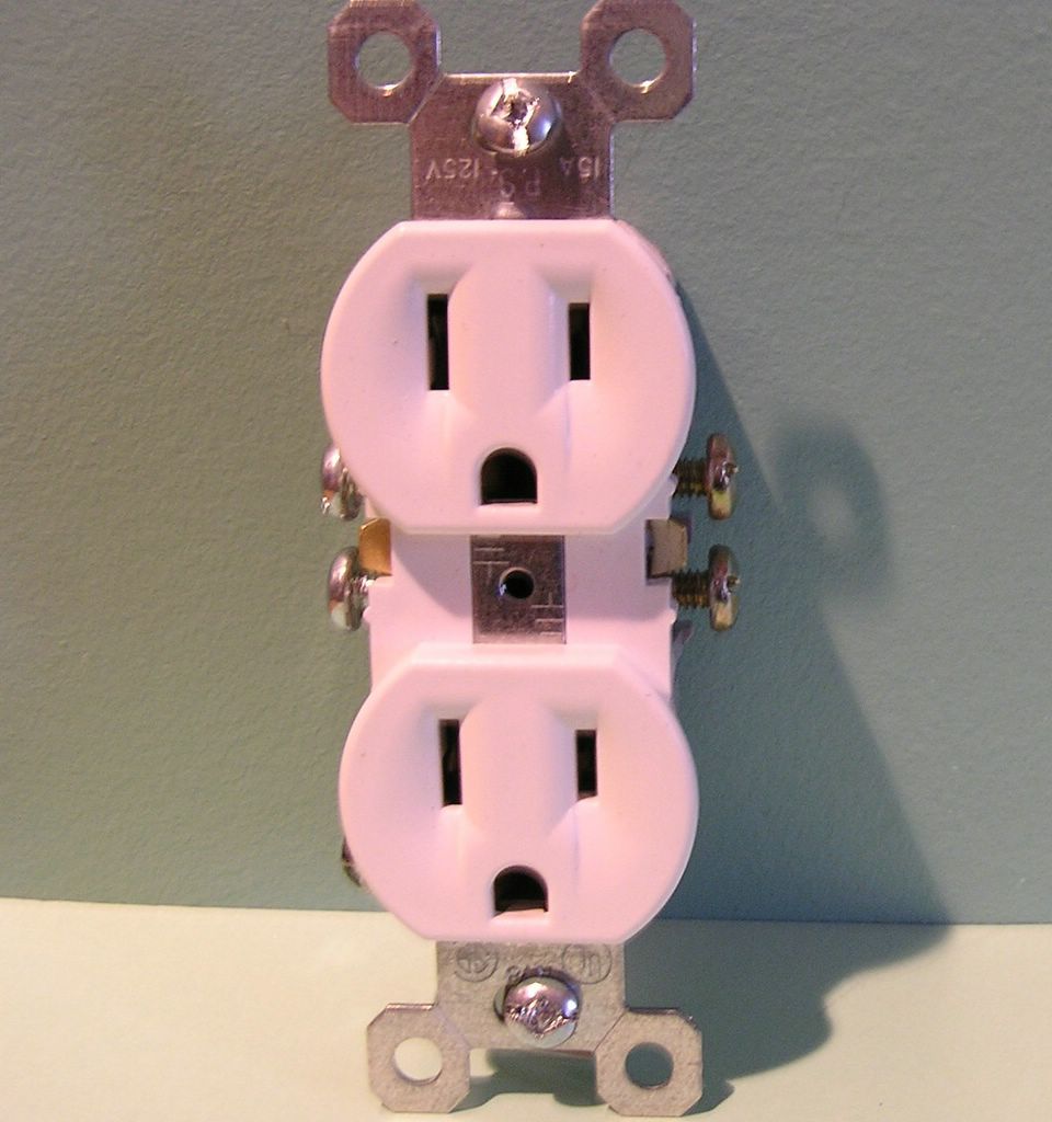
Traditional Duplex Receptacle
DO-IT-YOURSELF!
David’s Credo For Performing Electrical Work:
- Always disconnect the electrical power to what you are working on, turn off circuit breakers or unscrew fuses, use a voltage tester to be sure the power is off.
- When working within electrical boxes, make sure all of the wires and devices in the box are without power, use a voltage tester to be sure that power to every switch, and/or conductor is without power.
- Always replace electrical box covers when you are finished working with them, especially the electrical service panel cover.
- It may be necessary to pull the conductor(s) off the terminal at the fuse or circuit breaker to ensure that the circuit stays off while you are working on it.
- Tag the fuse or circuit breaker off, so that another knows that you are working on the electrical system.
Replacing Grounded 15 and 20 amp 120 volt receptacles with Ground Fault Circuit Interrupter receptacles (GFCI’s), in kitchens, bathrooms, basements and garages. The Key Word here is Grounded, as in a separate conductor, under the screw in the Electrical Box and connected to the Green Ground Screw of the device(s).
Starting in the bathroom, with the vanity receptacle, locate the circuit breaker or fuse for the existing receptacle you intend to work on and turn it off. 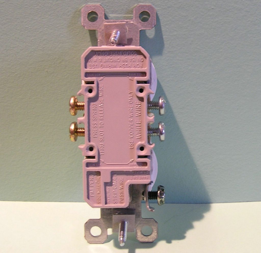
Traditional Duplex, Rear View. Begin by unscrewing the plate screw and plate and set them aside. Loosen and completely remove the two 6/32 flat head screws at the top and bottom of the device yoke, which hold the device in place. Grasp the receptacle on the sides (this is where you’ll want to be sure there is no power there!), and, with your thumb and fingers, pull the device straight out of the box. The conductors connecting the device should be of sufficient length to allow you to pull it out far enough so as to loosen the terminal screws. Loosen the terminal screws and lift the conductors off of the terminal post. Discard the old receptacle.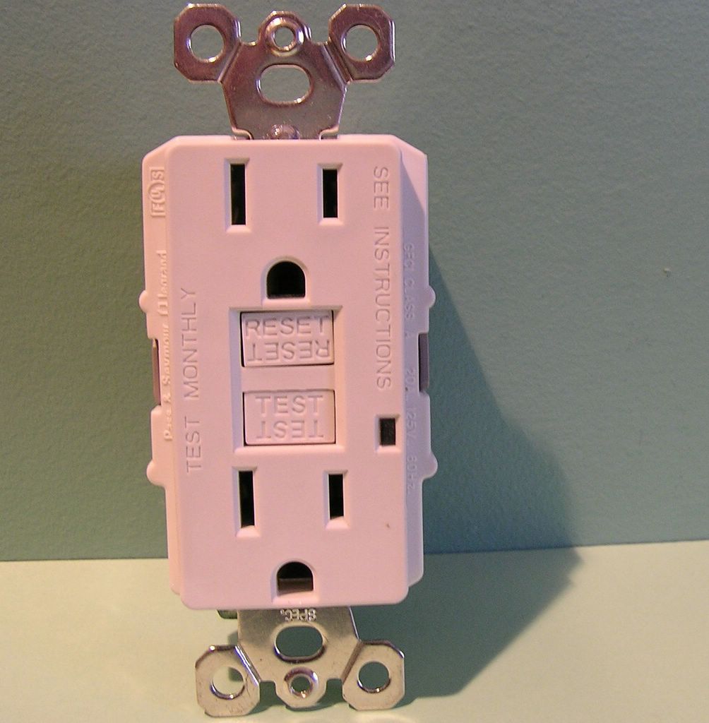
GFCI Receptacle
size:100%;color:#ccccff;">For now, let’s just assume that this receptacle had only a single cable feeding it, therefore, there will be a black, a white and a bare copper ground wire to connect to the new device. These connect to the brass and silver "Line" terminals, as well as the Green Ground Screw on the GFCI.
If there are two cables in the box, take the two white conductors and push them into the designated holes on the back of the GFCI and tighten the silver screw, likewise the two black conductors and tighten the brass screw.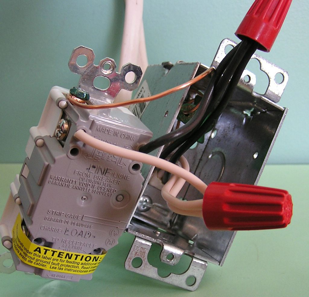
Splices, Pig Tails And Wirenuts.
If there are only screw posts, and no slot or hole for the two conductors, it will be necessary to splice the two cables together, simply pair off the two white conductors and a third "pigtail", or a small length of the same conductor material. Strip and splice the three whites together, wrapping clockwise and use an appropriate wire nut, yellow or red, depending on the wire size. Repeat this procedure with the two black conductors, the pigtail and wire nut as above. These pigtails are then connected to the device terminals, white to silver screw, black to brass screw, on the "Line" side of the GFCI receptacle. This GFCI receptacle configuration will trip whenever a faulty cord connected appliance or tool is plugged into it.
Now, let us review the full function of the GFCI receptacle, and remember that there are actually four terminal screws on each GFCI receptacle, two silver, and two brass. As I said earlier, there is a strip of tape, covering the "load" side terminals, white and black. 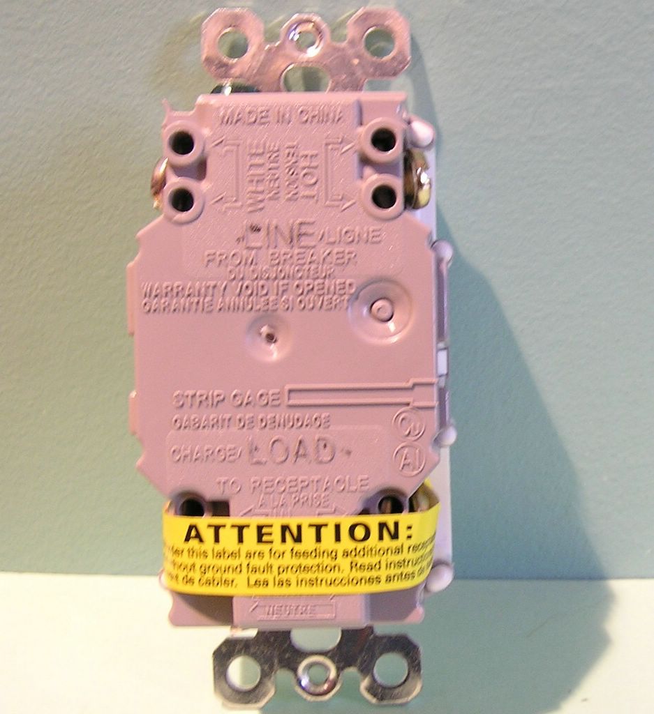
GFCI Receptacle, Rear View
What are these extra terminals for you ask? They represent the load side of the GFCI device, which means that any other device, connected to these "load" terminals will also be GFCI protected. So, this means that you can protect GFCI another receptacle, or series of receptacles, as long as they were connected to these "load" side terminals.
Therefore, if you have two cables in each box, you can put in one GFCI receptacle and connect the other "normal" receptacles to it to get the same GFCI protection. Aside from having to find the tripped device, once it does trip, it makes it easy to protect a number of receptacles in your home, using a single GFCI device.
After you pull a fuse that shuts off a receptacle that you want to replace, find out which other ones have power now, and which ones are dead. Check all of the receptacles that are off in the area you want to protect, leave the power off and pull the receptacle closest to the Electrical panelboard. Remove a pair of conductors in the same cable that connect to the receptacle, push them aside and put small wirenuts on them, make sure they are not touching anything else. Turn the power to the circuit back on. Test the set of conductors that you have the wire nuts on, for power, and then check the conductors still on the device, is there power in the device, or the free conductors? Do the other receptacles operate? If they are all off, you have found the homerun for the circuit, if not, turn the power off and reconnect the first receptacle as it was when you found it. Leave it out of the box, but tape up the device for the safety of others if necessary, and move to the next receptacle, repeat as before. When you do find the homerun, the cable that feeds from the panelboard, it should be connected to the set of live conductors on the "line" side of the device, white to silver, black to brass. The second cable, going out of the box, feeding the rest of the circuit, would then connect to the "load" side terminals of the device.

Linesman Pliers, Offset Diagonal Cutting Pliers, Needle Nose Pliers and Wire Stripper.
Once the all of the conductors are connected to the device, fold them back into the box as you push the receptacle back into the box, until you can line up the yoke screws and get them started into the screw holes of the electrical box. Push the device in as you tighten and don’t let the screw pull the device in, as you will warp the yoke. Attach the new plate, usually supplied with the new device, with the two screws provided.
Tip #1: Finding the right fuse: There are a number of ways to do this, from shouting back and forth to a second party at the fuse panel, as they pull one fuse after another, or the use of walkie-talkies. If you are alone and want to save time, try plugging in a small electrical tool, which makes a little noise like an electric razor or hair clippers, small electric drill motor, etc.. As long as you can hear it from the fuse panel location, you’ll be all set, simply pull fuses and listen.
Tip #2: Connecting the ground wire: The bare conductor should be passed under the 10/32 green screw in the electrical box, and then on to the green screw on the receptacle. These connections are very important and if you fail to connect them properly you leave the device in much worse shape than when you found it. This is the number one fault of most amateur electricians, they don’t connect the wire if they don’t know what it does; if everything works without it being connected, who needs it? Beware, electrical grounding is the one electrical safety rule you should never break.
Tip #3: Terminal Types: Some GFCI receptacles, as well as other devices, have screw "posts" which you wrap the conductor around, using a fish hook bend in the conductor end, wrap the conductor clockwise and close the "u" with a pair of pliers or dykes. Make the connection firm, or as tight as you can without breaking anything. Other devices, switches included which have what look like floating washers, with a screw passing through the center, you may see the slots where two conductors can slide under the washer or into a conductor hole, on the back of the device, which are made also fast with a screw.
Tip #4: Screw Posts: Always wrap a conductor around a screw post in a clockwise direction, so that as you tighten the screw, the conductor is pulled into a tighter circle around the post. In the alternative, counter clockwise direction, the conductor is pulled away from the post; loosening the connection.
Tip #5: Stab connections: Never use the stab in connections (look Ma, no screw) on any electrical device, it is not legal!
Tip#6: Terminal colors: The black conductor connects to the brass screw on the new receptacle and the white conductor connects to the silver screw.
Tip #7: Markings: A GFCI receptacle is marked "Line" and "Load", with a piece of tape, usually yellow, that covers the terminals on the "Load" side of the device. If you have just one cable, with a white, a black and a ground conductor, connect to the exposed screws marked "Line" and leave the yellow tape in place.
Tip# 8: Finessing the Task: If the receptacle is not fitting snug against the wall surface, it may be necessary to break of the tabs on the receptacle, which are delineated by creases, they look like small washers once you cut or pry them free. Bend them back and forth, or cut them at the crease, and this will allow the device to go back further into the box and the plate to fit flush against the wall.
Tip #9: When trying to lift conductors off screw posts: It may help to apply a little leverage by using a pair of pliers, grasping the conductor on the insulating plastic covering and prying against the device back, to open the fish hook around the terminal. If you hold the conductor tight and not let it slip on the insulation, you won’t tear the plastic covering.
Tip #10: Never put two conductors under one screw terminal, it is unlawful!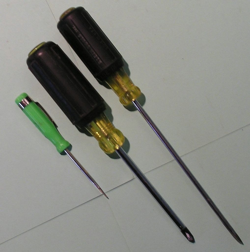
Miniature, Philips Head and Straight Blade Screwdrivers.
posted by David @ 2:00 PM
![]()
![]()
0 Comments:
Post a Comment
<< Home