
Installing Dimmer Switches
Before I begin this lighting dimmer installation guide, you must read this little ditty first.
- Always disconnect the electrical power to what you are working on, turn off circuit breakers or unscrew fuses, use a voltage tester to be sure the power is off.
- When working within electrical boxes, make sure all of the wires and devices in the box are without power, use a voltage tester to be sure that power to every switch, and/or conductor is without power.
- Always replace electrical box covers when you are finished working with them, especially the electrical service panel cover.
- It may be necessary to pull the conductor(s) off the terminal at the fuse or circuit breaker to ensure that the circuit stays off while you are working on it.
- Tag the fuse or circuit breaker off, so that another knows that you are working on the electrical system.
We begin this installation installment by identifying the switch that controls the lights that you want to dim. Identify the need for a Single Pole switch (only one location to switch from) or a 3-Way switch (two locations , or more, to switch from). Proceed by removing the switch plate screws and the plate itself, and loosen the two screws, top and bottom, that hold the device into the electrical box. Pull the device out of the box by grasping it with your thumb and two fingers, if the power to the circuit isn't off, this is when you will find out!
At this point in time, with the old switch literally in-hand, you can determine the type of switch you have. If there are only two conductors connected to it, it is a Single-Pole switch, and can be readily replaced with a Single Pole dimmer. If the switch has three conductors connected to it, it is a 3-Way switch and can be readily replaced with a 3-Way dimmer! If you find four conductors connected to the switch, you have a 4-Way switch. If you picked this as a location for your dimmer switch, you must choose another. You cannot replace a 4-way switch with a dimmer!
Once in-hand, unscrew the post terminal screws until they will not loosen any further and stop before you unscrew them completely (these are known as "captive" screws, in that they will not back out completely and should be left in-place). Disconnect the conductors wrapped around the screw terminals by grasping the insulated portion of the conductor, and, without slipping and damaging the insulation, pry against the body of the device to open the hook. Lift the conductor off the terminal and reset the hook on the conductor end. The grounding conductor, either bare copper, or green insulation, must also be disconnected. The green ground screw is also a "captive" screw, do not dislodge it by unscrewing it too far. Once loosened, pry the conductor off the treminal as before.
If the conductors are stabbed into the back of the device, which is a no no these days, you will need a small straight-bladed screwdriver. You will find, next to the conductor opening on the back of the device, a small slot (this slot should accept the blade of the small screwdriver you have chosen). Insert the blade into the slot, and, while pushing on the screwdriver, pull the conductor out of the opening. You may have to wiggle it free, but it should come out fairly easily. If you have to cut the conductor, leave as much length on the conductor as you can, it will make the installation simpler. If you find the insulation on the conductor is brittle and cracks when distorted, this may be the result of a loose connection, check that the conductor itself is not also discolored and brittle. Loose connections allow to breed a myriad of troubles, not the least of which is that old favorite, excess heat.
The new dimmer may have terminal screws, like the switch it is replacing, therefore you can reuse the hook on the new device, or fashion a new one. If the dimmer has pre-stripped leads, you can cut off the hook, or a portion of it, to facilitate connecting the stranded conductor to it.
Assuming a single pole switch replacement, connect the two wires that you took off the switch to the terminals of the dimmer switch, if the dimmer has wire leads and not terminal screws, wrap the bare, stranded conductor around the black or red conductor, clockwise, and complete the splice with a wire nut, appropriately sized. Make sure that the wirenut covers the bare conductor and is seated tightly on the conductor splice. I find it works best if you don't twist the stranded conductors together, rather wrap them around the solid conductor in a more or less flat, ribbon-like fashion, cut off any excess strands and secure the coinnection with the wire nut.
3-Way dimmer switches are only a tad more complicated than the Single Pole dimmer switches to replace. But, you have to know two things when hooking up a 3-Way switch, or dimmer device, which two conductors are the "travellers" for the 3-Way switching system, and which single conductor is the "point"?
Follow the steps above for pulling a switch out of an electrical box, and, with switch in-hand, take note of the terminal screws on the switch. A 3-Way switch will have two like-colored screws, usually brass colored, with the third terminal a darker shade, almost black. The two like-colored screws are the "travellers" of the 3-Way system, carrying the power to the other switch, or switches. The third, black terminal screw is the "point", which, in electrician-speak means the return to the light, switch, or system. The 3-Way dimmer will usually have two red leads, and one black lead. Connect the two red leads to the two traveller conductors, and the black lead to the third conductor which you took off the old switch. Connect the 3-Way switch or dimmer any other way and it will not operate properly. If you are going to install, two dimmers, in the same location and electrical box, I will show you how this done.
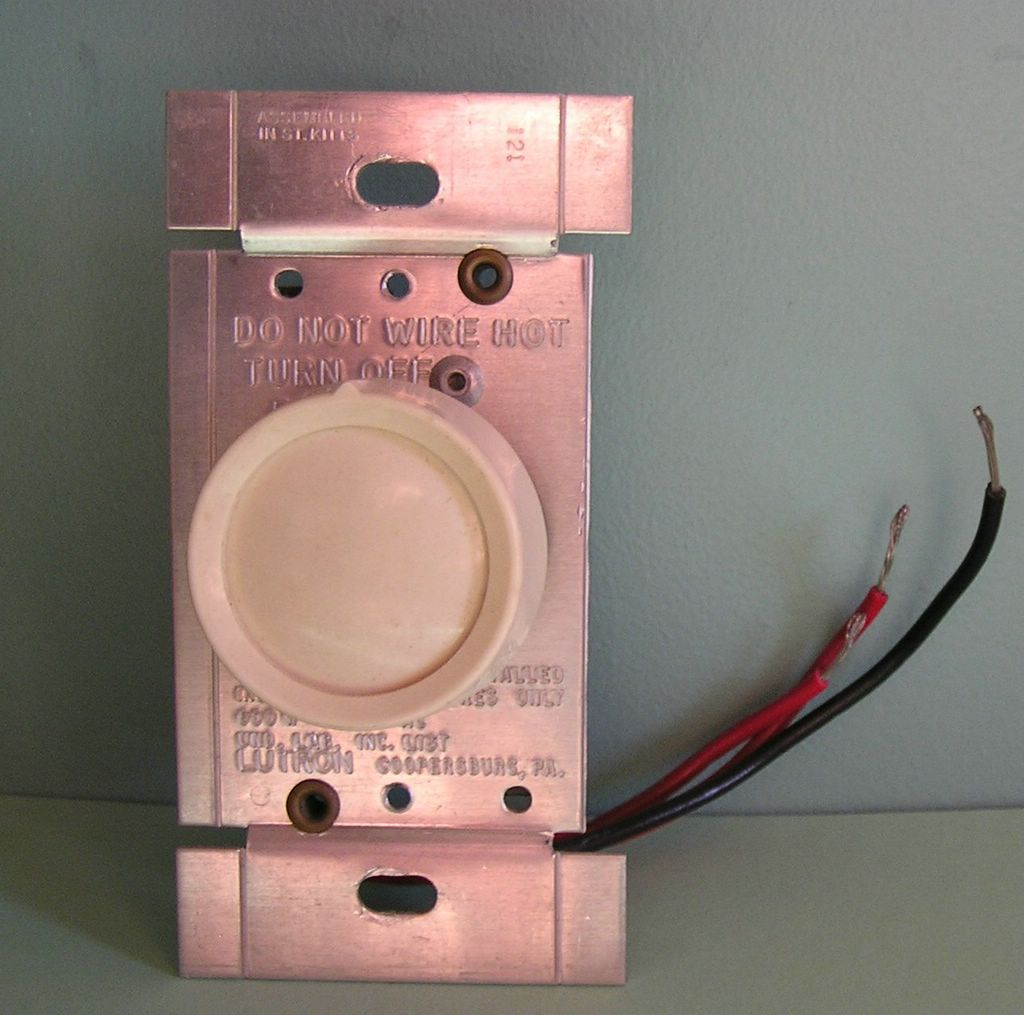
Notice in the photograph of the rotary dimmer switch, that there are creases down the side of the aluminum device strap, or plate. These extra bits of aluminum help to cool the dimming device, by enlarging the exposed area of the aluminum plate. These may be systematically removed, as one of these flaps has been taken off the right side of this particular dimmer pictured (I told you it was preowned). This was done to allow for the installation of multiple dimmers side-by-each, in a 2-gang or larger switch box. These extra aluminum "heat sinks", as they are referred to, since they drain away the excees heat the dimmer's electronic circuitry produces. They can be easily removed by simply bending them back and forth until metal fatigue takes over and the joint breaks. You can take alternating heat-sink pieces off, to match with the dimmer mounted to either side, as shown by the next photograph.
Here I demonstrate the way to "gang" these devices in a switch box. You will want to be careful that you don't strip all of the tabs off of a single device, but rather to remove a few tabs off of all devices, alternately.
posted by David @ 10:15 PM
![]()
![]()
0 Comments:
Post a Comment
<< Home