
Rough Wiring Segment
The Walk Through Is Through
With the Walk-Through complete, the final layout of the electrical system can begin, even if there are a few details to iron out. At this point the rough-in wiring of the house’s electrical systems can begin.
On Your Mark, Get Set, Wire!
I always start my wiring jobs in the area the furthest away from the electrical panelboard, from which all the electrical feeders and branch circuits within the house will originate. If there is a sub-main panel board, this is where some of the branch circuits will originate; a sub-main feeder from the panelboard supplies power to it.
Remember these words "feeder" and "branch circuit", they are very important, distinctive and descriptive words. The definition of a feeder is: All circuit conductors between the service equipment, the source of the separately derived system, or other power supply source and the branch-circuit overcurrent device. The definition of a branch circuit is: The circuit conductors between the final overcurrent device protecting the circuit and the outlet(s).
There are also several types of branch circuits within a dwelling, or for that matter in any building being wired.
- An Appliance branch circuit is one that supplies energy to one or more outlets to which appliances will be connected and has no permanently connected luminaires (light fixtures) that are not part of an appliance.
- A General-Purpose branch circuit supplies two or more receptacles or outlets for lighting and appliances.
An Individual branch circuit that supplies only one utilization equipment. - A Multi-Wire branch circuit consists of two or more ungrounded conductors that have a voltage between them, and a grounded conductor that has equal voltage between it and each ungrounded conductor of the circuit and that is connected to the neutral or grounded conductor of that system.
A large building may have a main service panelboard and a sub-main panelboard at a different location, as part of the electrical distribution system. Some of the largest buildings will have many feeders and sub-main panelboards, spread throughout the building. In this way, all of the circuits (home runs) do not have to originate in the same panelboard. Our small house, has only the main service panelboard, where each and every circuit in the building will originate.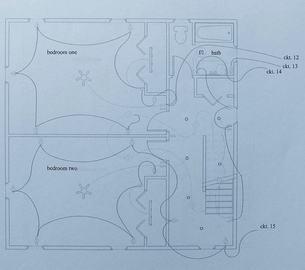
Click On Plan To Enlarge
Bath GFCI Receptacle
Notice that Circuit # 13 feeds the GFCI receptacle in the bathroom, and per NEC will be served with 120 volts, 20 amperes. Hair dryers, curling irons, all use more electricity than your electric toothbrush charger, or an electric razor.
Bedroom Circuits And Smoke Detectors
Circuit # 12 is for receptacles and fan, as well as the closet light and receptacles in Bedroom One, but, can you also see the heavy line to the smoke detector, from that same bedroom circuit? That is the “power feed” for the detector system. This is a common way to feed the smoke alarm system, in that the fire detection system is required to be fed from a lighting circuit, instead of a circuit alone and by itself. The thinking behind this rule is, if the homeowner, tenant, or occupant wants to turn the smoke detectors off, they must also have the inconvenience of losing a lighting circuit. In this way the homeowner isn't as liable to turn the smoke detectors off and leave them off indefinitely.
So, in this case bedroom one is the master bedroom and, if circuit 12 were turned off, there would be no power in that master bedroom, no fan, no lights, no television, nothing but darkness. Get the point? In most cases the detector can be taken down by the homeowner and reset, you'll see how shortly.
Battery Back-Up
These days the smoke detectors we install are self-contained, with battery back-up, in the event of a power failure. This is an excellent way to ensure fire detection coverage even when the power is off! But, the batteries don't last forever, so if your own smoke detector in your present home is chirping at you, it is usually but not always an indication that the battery needs to be replaced.
It is always recommended that you replace all of the batteries in all of the detectors at the same time. Ergo, if one battery is dead the others can't be far behind. Local weathermen usually insist we check our smoke detectors batteries each time we toggle between Standard Time and Daylight Saving Time, in the Spring and Fall. What is that, Fall down Spring up, no, Spring forward, Fall over, or is it Fall back, Spring forward? Whatever, remember to change the batteries in your smoke detectors!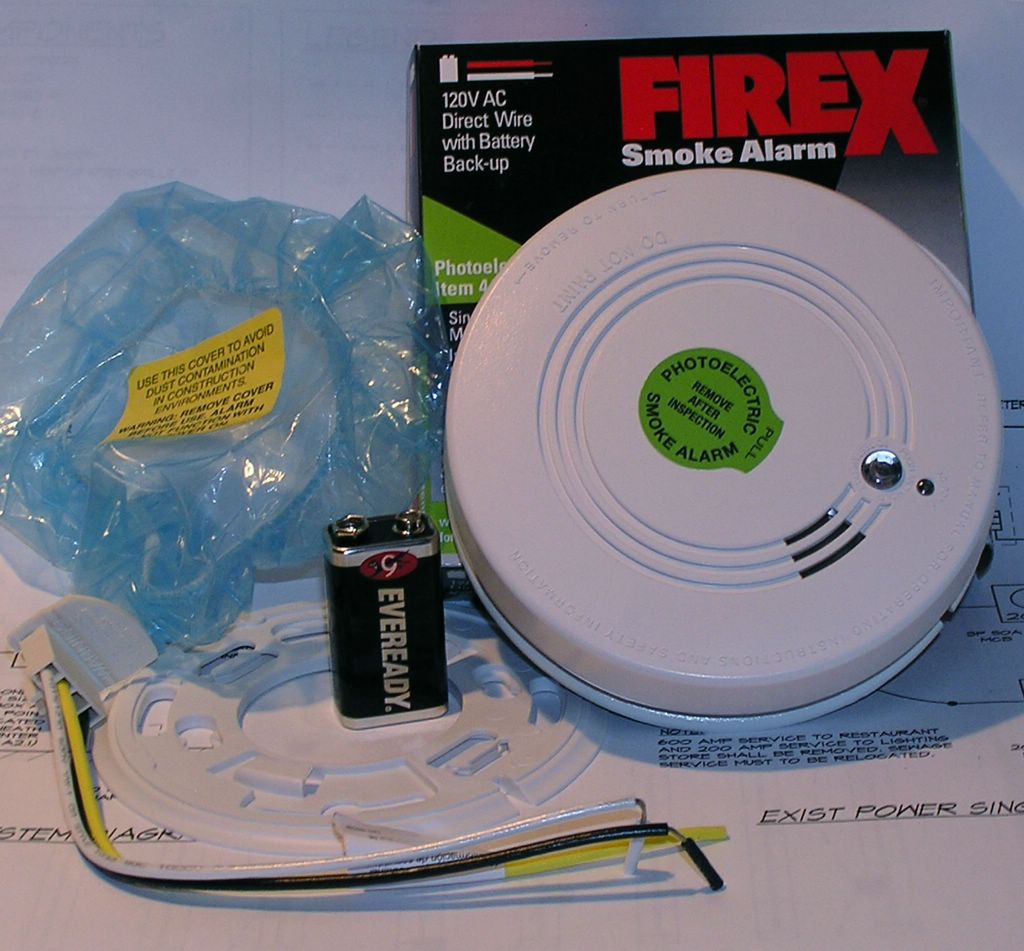
Pictured is a Firex brand smoke detector, notice the base plate, the wiring pigtail which plugs in to the back of the detector and the "bathing cap" for added protection from dust and paint during periods of construction, cute eh? The cap must be removed after the dust has settled for the unit to properly function.
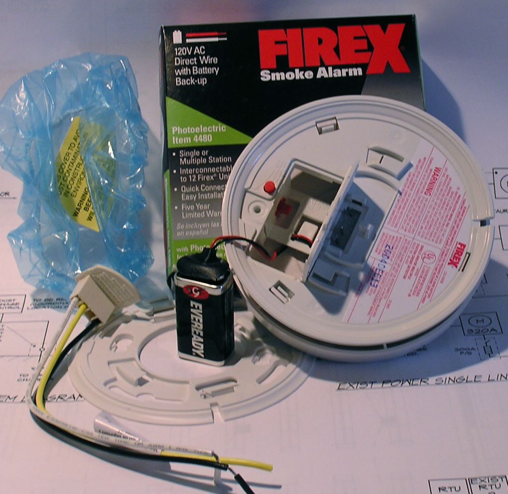
smoke detector, rear view
This view of the back of the unit, which shows the battery compartment, this model number 4480, note it uses a 9 volt radio battery, the one with the male and female snaps for terminals.
Interconnected And Loud
Each of these smoke detectors has to be hard-wired together, or daisy-chained, so that they alarm in tandem with one another; so if one goes off, eventually they all will go into alarm mode and nearly shatter your eardrums at a sound level of at least 8.5 decibels, the minimum required audio level. Okay, so it won't shatter your eardrums, but it certainly will wake you up!
Re-Setting A Smoke Detector that Has Gone Into Alarm
To clear a smoke detector that is in alarm; that is not involved with a fire, simply turn off the circuit that is feeding it for several moments. Allow the smoke chamber to clear, and, via the printed circuit board, reset itself. If when the circuit is re-energized, the detectors still will not reset, it may be that one or more of them are dirty, contaminated, or simply have an insect crawling inside them (a common problem).
Placement Of Detectors
Notice the lighter lines (representing cables) connecting the smoke detectors in the bedrooms, hallway at the base of the attic stairs and on up to the attic, if a detector is required there in your town. From the light switch, there is a cable for the attic light. Note also that the other end of the smoke detector system the cable heads down the stairway to the first floor detector, mounted on the ceiling near the bottom of the stairs.
A Little Physics Lesson
It is common knowledge that hot air rises, as does the smoke from that incendiary source. Therefore the smoke detector at the ceiling of the lower level, near the base of the stairwell will be activated by the smoke wending its way to the second floor. This smoke, heated from the fire, rises to the ceiling and once there, spreads laterally across the ceiling. At the point where the ceiling meets the wall, there is what is known as a dead zone, in regard to the smoke and the now-heated ambient air. This "dead" zone doesn't allow the air currents to reach all the way into the corner, therefore it is best to mount the detectors at a minimum of 12" away from adjoining walls, and, for cathedral ceilings, three feet down from the highest point. The same law of physics applies here, in that eventually the super-heated air will fill the airspace at the roof peak, and actually block out the smoke, rendering useless a detector mounted at that level.
Cleaning Smoke Detectors
Cleaning smoke detectors is a project you, the homeowner, can do yourself. It is always best to take the detectors down one at a time. They all unscrew or twist counter-clockwise from there ceiling mount and unplug from the power source, with a safe and easy to operate plug-in mechanism. Use a vacuum cleaner to either blow or suck the dust or bugs out of the unit. Once cleaned, reconnect the plug and reinstall them as they were previously.
Once all detectors are installed, the Smoke Detectors must be tested for functionality. On the face of each detector there is a small push button for testing the detector. Pushing this test button should activate the smoke detector in your hand first; holding the button down until you can hear all of them chime in together is a simple way to ensure your family's protection from a fire. Releasing the button will allow the detectors to recover by opening up a relay in the detector itself; it may take several minutes before they are completely silent.
Fire Inspection
The building department, or fire inspector, will schedule an actual fire test, by introducing smoke directly to the smoke detector with a smoking torch. He will then check that all of the detectors are ringing, as is the code.
The electricians begin on the second floor, by first nailing all of the electrical boxes in their respective receptacle and switch locations as per the electrical plan (e-plan). From the e-plan can be identified all of the elements included, and these elements are then transcribed to the wall studs of the building, usually with a felt tip pen. The electrician would go around and mark an S1, S3or S4 on the stud closest to where each item, the switch, light or receptacle, would be mounted. Remember that we are talking about wood studs and that these are usually set at 16" on center and our 'locationing' is limited somewhat by support members that cannot be drilled through, chiseled into, or removed entirely.
Receptacles can be mounted at virtually any height, but, to comply with NEC an outlet must be mounted below 5'-6" to be considered a required receptacle. Receptacles serving the kitchen countertop, a bathroom vanity, or wet bars can be a maximum of 18" above the counter, vanity or wetbar to be the required receptacle. That said, we follow these general rules, but each individual electrician has their own mounting heights for these different units.
Hammer Height?
In new construction, I ask the guys to mount the receptacles at 14" to 16" above rough floor, or hammer-height, as long as the installer use the same hammer in each room, of each house, bar none.
Hammer-height is achieved by placing the box against the stud we are mounting the electrical box to, lining up the depth of the wall covering with the gauge that is etched on each individual box. By laying the hammer head on the floor, with the handle held vertically against the chosen stud, the box can be set atop the handle for the height. Each hammer manufacturers length varies by an inch or so, from tool to tool, but they are all roughly 14 - 15" long.
Switch boxes I like to mount at 42" above the rough floor, or 41-3/4" above the finish floor. This may vary from room to room, to accommodate special wall treatments like wainscoting, beaded paneling, or some other architectural feature that must be recognized and reconciled into the placement of these devices.
If we are doing a remodeling job, or partial renovation, I try to match the existing switch heights within the original structure. As to the receptacles, they can also be mounted in the baseboard, or mockboards, to remain unseen as they perform their function for compliance and convenience. Or, they can be mounted to match the existing detail of the building being remodeled.
Telephone, Cable TV, and Data locations can follow the receptacles and be mounted at so called hammer-height, or be in the baseboard. In the kitchen, they can be mounted at the counter top height, matching the switch height for general congruity, or you can have a wall-hung telephone, mounted at 60 or so inches above the floor, 24" above the counter top. As with most everything else these days, telephones are cordless, everyone uses answering machines, and, if you have a data line you have a PC; therefore, it is a good idea to place these data, telephone and catv outlets next to a duplex receptacle, or, in the alternative, place a duplex receptacle next to them!
After the rooms are marked out for the boxes, and the boxes are all hung, 1-gang for the receptacles, some 2-gang boxes, as well as some 3 or 4-gang boxes for the switches. The rooms are then drilled-out for the non-metallic cable (romex) that will course through, between and behind the buildings inner sanctum; the framing and finish construction components.
Usually a single hole is drilled above every single switch or receptacle box (1-gang), two holes for a double switch box (2-gang), etc. If some of the switch and outlet locations are accessible laterally, through the adjoining studs of a wall, we drill horizontally only when it makes sense to do so. No matter how the wall and ceiling members are drilled out, each hole must occupy the center of the framing member being drilled through. Also, when stapling the romex, the cable must not ever be closer to the finish side of the wall than 3/4". These rules are an effort to prevent a cable or group of cables being pierced by a nail or a drywall screw. In the case where the wire is run closer than these guidelines, a metal plate must be used, of at least a 1/16" thickness, to prevent this hazard.
Remember, that if a nail or screw pierces the cable, and doesn't trip the circuit breaker, that nail head or screw head is now electrically alive. If you were to paint over a screw that is so-energized, especially with latex, water-based paint, you would receive a small shock. I know this first hand!
The electrician and his apprentice continue to mount electrical boxes, for the various devices, switches, receptacles and light fixtures. The second floor has the recessed lights in the hallway, a fan & light unit in the bathroom, one closet fluorescent in each bedroom closet and the smoke detectors.
Click On Plan To Enlarge
Once the switch boxes, recessed lighting frames, ceiling boxes and smoke detector boxes are all mounted, and the holes are bored throughout, the electricians will then start to pull in some of the cables for the connection of the various elements that comprise the electrical system. So, as they prepare to start pull the circuits, switch legs, light returns, cabling for the smoke detectors and 3-Way light switching systems, I will explain the tasks at hand in more detail.
Before I go there though, I should explain to you the cable assemblies themselves, how they are constructed; what they are designed to do. This is a many faceted subject, that I will explain here briefly, as well as make other references and add further explanations of their make-up and uses for you, as we go along.
American Wire Gauge, or AWG, is a standard for conductor size, adopted as American Standard early in the developmental stage of wire and cable manufacturing. For all intents and purposes, we will be talking mainly about the following AWG sizes in the residential wiring sphere, I will list them by size and briefly explain the uses of each. Keep in mind that the lower the number, the thicker the AWG size and the higher the amperage they can carry. For the intention of this article, only copper conductors are being discussed, unless stated otherwise. Starting at the bottom, from small to large:
- Thermostat wire, or low voltage control wire, comes in both 18 and 20 gauge, with configurations of up to 8 multiple conductors. An 18 gauge, two conductor cable is expressed as 18/2; a 20 gauge, three conductor cable is expressed as 20/3, etc. Ergo, gauge / conductors. As the name implies, these cables are used for thermostats and controls such as garage door openers, doorbells and buttons, furnace wiring, zone valves and dampers, among other uses. Thermostat wire can be used for voltages up to 300 volts (between conductors), but generally in the uses mentioned they carry only 16 volts for your door chimes; or up to 24 volts for your heating or cooling thermostat.
- Non-metallic sheathed cable (romex) is available in gauges from 14 to 2, with configurations of up to 4 multiple conductors, plus a grounding conductor. A 14 gauge, two conductor cable is expressed as 14/2 Romex; a 2 gauge, three conductor cable is expressed 2/3 Romex. Not expressed, but none the less included in the cable, is the grounding conductor. These cables can be used to wire receptacles, lights, switches, small appliances, etc., mostly used in wood frame construction.
- Service Entrance Cable (SEU) or (SER), comes in gauges from 10 to 4/0, in configurations of up to 4 multiple conductors, and a grounding conductor. A 10 gauge, two conductor cable is expressed 10/2 SE; a 10 gauge, three conductor cable is expressed as 10/3 SER. . The 2-conductor cable is called SE cable, for Service Entrance, the 3 or 4-conductor cable is called SER cable, for Service Entrance, Round. The 2-conductor is more or less flat, or oval cable, and the SER is round. These cables are used excusively for service entrance conductors, usually installed from your electric metering equipment to your panel board. SE cables can also have aluminum conductors; they are also sunlight resistant.
- Metal Clad, (MC) cable is available in gauges from 14 to 2, in configurations of up to four conductors plus a grounding conductor. A 2 gauge, three conductor cable is expressed as 2/3 MC cable; a 12 gauge, 2-conductor cable is expressed as 12/2 MC cable. The sheath is made of either steel, or aluminum. MC cable is used in rough service areas, where a flexible cable is preferred, on heating and cooling equipment and controls.
- Underground Feeder, (UF) cable is available in gauges from 14 to 2, with configurations up to four conductors and a ground conductor. A two conductor 14 gauge cable is expressed as 14/2 UF, etc. UF cable is used in direct burial conditions, for post lights, ground lights, for feeders and branch circuits; UF cable, like SE cable is also sunlight resistant
All of the cables above are constructed similarly, with the insulated conductors and the uninsulated ground conductor sheathed in an outer wrapping of plastic, aluminum or steel (MC cable). Each of these cable references assumes the inclusion of a grounding conductor, even without actually stating that this is so.
posted by David @ 4:02 PM
![]()
![]()
2 Comments:
David,
I came across your blog while doing a search on Yahoo. I was wondering if you had time to offer some advice before I hire an electrician to come to the house! We moved into our home over a year ago and have been trying to do most of the upgrading ourselves. We bought an electric clothes dryer recently, only to realize that the previous owners must have had a gas dryer, as there was a gas line to that part of our basement. Neither I nor my boyfriend know much about dryers... so, once getting the dryer into our basement, we found that the plug doesn't match the outlet. The outlets are standard, but I'm guessing the dryer must need more energy or something? (I really know nothing!)
My question is, can we install or convert our outlet into something that would work with our dryer? Do we need to hire someone, or can this be done fairly easily? (My boyfriend is quite handy in home repairs as are some of our friends, but this is a first for us.) Do you have any advice or links, anything? I truly appreciate your time, and thank you in advance!!
Megan
Megan,
The electric Clothes Dryer operates on 120/240 volts and is required to have a 30 amp receptacle with a 4-wire cord to the dryer. If you bought your dryer new, it would likely come without the cord. The appliance dealer can supply one for you, or the electrician that you MUST hire to install this 30 amp 240 volt line will have one to sell you as part of his installation, be sure to tell him that you need one.
The existing receptacle, for the old gas dryer, was sufficient to handle the 120 volt / 15 or 20 amp load, but a new cable and receptacle must be installed from your dryer location to your electric
service (the panelboard). If you have a few spare circuits in there, and you have circuit breakers and not fuses, you're lucky.
If the dryer is a used one, and already has a cord, the old three prong cord must be removed and discarded. The new cord has to be grounded to the dryers steel frame with the green conductor. After the old cord is removed you must disconnect any other conductor that is under the same screw terminal as the white conductor, on the dryer terminal strip. Often there is a strip of steel, or copper band that is under that silver screw. This must be removed and discarded; the new green ground conductor connects to the frame of the dryer, under the same screw as the copper or steel strip.
Get an electrician to do the installation, he should know how to advise you further.
Good Luck,
David
Post a Comment
<< Home