
Rough Wiring, Continued
Pulling Cables
So, with the holes all bored out in the studs, plates and shoes of the walls, it is time to actually pull in some wire. Again, on the second floor, the various cable assemblies (e.g.: 14/2, 14/3) are "run out" to speed the installation time, as well as to keep the cables from twisting as we pull them through the bored holes. This is a process that can be simplified by buying an uncoiling device, such as the one in the photo, a sort of lazy susan on which the coil of non-metallic sheathed cable is placed. The cable is then threaded through the outplay arm, or bailer, to avoid tangling. The unit itself is held in place by a friction connection of two steel arms which straddle the wood framing members; actually designed for use with the vertical 2 X 4 framing studs, see photo.
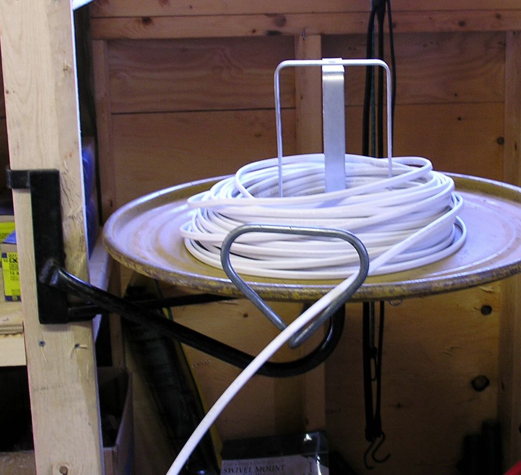
While the unit splays out the cable as you pull it, the spinning motion uncoils the wire just as it was manufactured (actually in the reverse), flat, kink free, and ready for stapling neatly along the framing members. Keeping the wire straight in this manner simplifies the installation, and keeping the wire straight is a much easier task than making it straight again once you’ve tied it in a square knot! I have been asked how I am able to do such a neat job of cabling and stapling; the answer is always the same, don’t foul the line and it won’t ever need untangling. (A bit of maritime humor here, I come from a long line of fisherman, beginning in 1848, in Gloucester, Massachusetts).
Beginning with the 14/3 cable, I will pull in the 3-way wiring for the 2nd floor hallway lighting. I drag a cable up through the bored hole above the 2-gang switch box at the end of the hallway, at the base of the stairs to the attic. Pulling across the top plate of the framed 2 X 4 wall, the cable is kept inside the framing members, woven under the ceiling joists and between the furring strips of the ceiling construction. Once the cable is pulled across the hallway, it is then routed in a manner parallel to the joists, above the furring strips, to the area above the electrical box for a 4-Way switch. The 4-Way switch, which is part of the upper hall switching system, is located between the two bedroom doors. It is then pushed down through the bored hole above the switch box, gathering enough wire to reach the switch box, plus an extra 12 - 14" of slack. To prevent pull back of the cable it is stapled to the wood stud, just below ceiling height. The cable is then neatly stapled parallel along the ceiling joist until it reaches the crossing point in the hallway. It is then stapled across the underside of the joists, to the location above the initial 3-Way switch. The cable can then be pulled back taut and cut to length, leaving 12 - 14" of extra cable.
This done, a second 14/3 is pushed up through the bored hole above the same 4-Way switch and it is led down the hallway, over the furring strips toward the bathroom, until it reaches a point across the hallway from the 2-Gang switch box. From there it is woven under the ceiling joists and pulled down through on of the bored holes in the wall plate above it. Leaving the appropriate amount of slack, the cable is then cut off and it is stapled back to the stud, again just below the ceiling level, to prevent pull back. Stapling the cable to the underside of the ceiling joists, the cable pulled taut as I go across the hallway, for neatness. I finish stapling the cable parallel to the joists down the hall and back to the 4-Way switch box. These cable staples are the insulated variety, so as not to damage the cable. These are staples we are driving here, not railroad spikes, we don’t drive them in so far that they cut into the cable (I’ve seen apprentices do this).
I am not going to demonstrate the installation of each cable in this way, but you get the idea that this is the way to run cable, parallel to the framing members where possible, following the contour of the object being traversed, crossing at right angles otherwise. Always follow this method, keeping the cables parallel to the members and stapled back, away from the finished surface by 1-1/4", per NEC rules. For cabling in basements, running across ceiling joists is limited to # 6 AWG or larger (the smallest allowable size / conductors in the cable).
If I show you the 2nd floor circuit layout, you can see how we might feed the various devices.
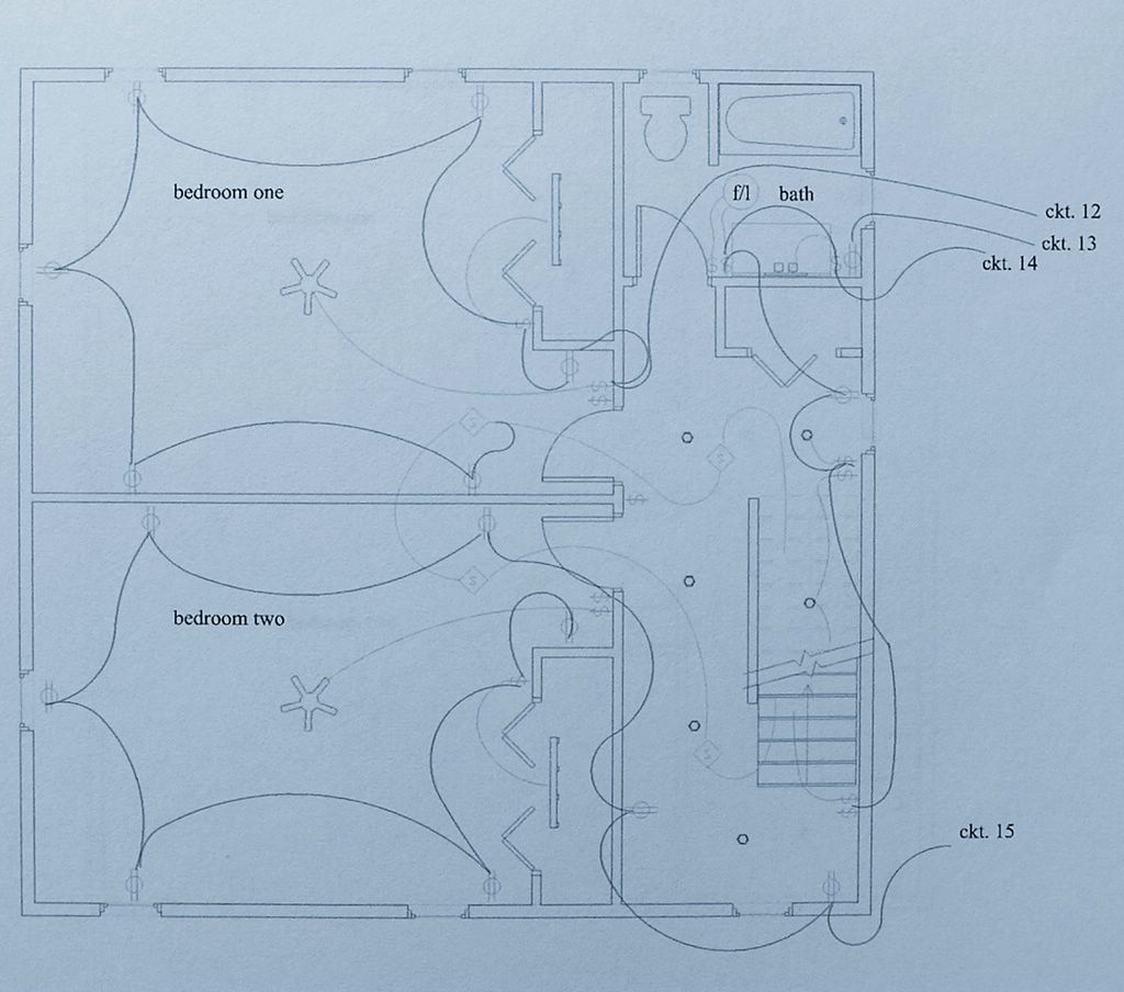
The single, darker lines between items depicts a 14/2 cable, as it enters, and sometimes also leaves each electrical box, at every duplex receptacle location, as well as some of the switch boxes. No, these items are not wired like the old Christmas tree lights - where if one lamp goes out - they all go out, that would be a series circuit. These various electrical load devices (light bulbs in lamps plugged into wall receptacles) are wired in parallel, but they are none the less on the same circuit! If the circuit breaker trips, or if a fuse blows, the entire circuit will go off (eight or ten electrical items) and nothing on that particular circuit will function.
Trouble Shooting With Ease
A key factor to understand and consider when doing your own electrical system work, and that is the fact that every wire, connection or device is part of a larger schematic diagram. Therefore if any of these elements fail to perform, the electrician may have to search through every electrical box, checking splices and such - while trying to troubleshoot, and therefore it sometimes does take some time to determine the source any problem. Believe me, for a professional like myself, finding trouble in a circuit that has been tampered with, either by the homeowner or an otherwise inexperienced person, is up there with the most time consuming and frustrating of endeavors! Nothing that the novice has done makes any sense to the pro, not the order, the method or the end result.
Existing Electric Wiring & Remodeling Or Renovation
You should consider that the licensed electrician responsible for the existing wiring in your house probably knew what he was doing and interconnected the various electrical elements according to accepted codes and practices, at least those codes that were in-force at the time of the initial installation. (most licensed electricians are well qualified, no matter how immensely unsung their feats; the least of which include hazard and intrigue) Therefore, the electrical cables running in between the studs and joist of your home, are a portion of those many circuits.
Circuits Interrupted
When a renovation project requires that a new window or a new door (or the old in a new location) be installed, a cable or series of cables might be found in the wall cavity in which the new opening is to be located. They might be serving other needs besides those in that particular room; the found cables could run to the 2nd floor, the basement, or elsewhere in the building. Interrupting the circuits (severing any cables) would cause the loss of power to all or some of the devices and/or utilizations that are a portions of any particular circuit. For this reason, remodeling or renovation electrical work is more costly than similar tasks being performed on new buildings; especially while under construction.
Feed Through Devices
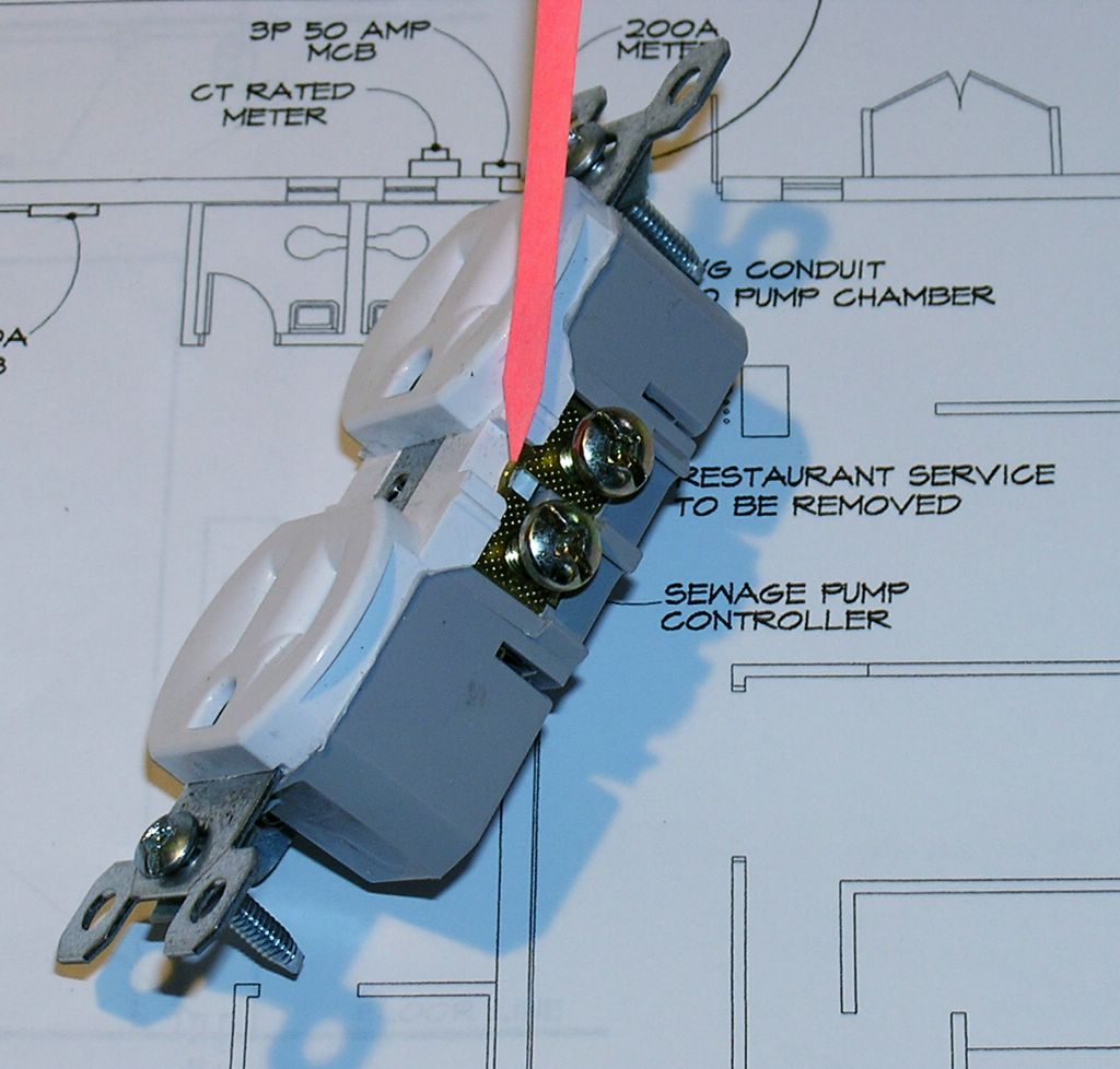
duplex receptacle, traditional, showing removable tab
In a duplex receptacle location, the conductors are connected to the duplex receptacle on one set of terminal screws (black to brass & white to silver) and fed out of the receptacle on the other set of terminal screws, these receptacles are therefore connected in parallel and are known as feed-through devices. There is a "tab" connecting the two screw terminal screws to each other; break off that tab, the connection is broken, and the device ceases to feed out to the next receptacle or electrical device. We use this broken tab feature to enable a switched receptacle, and, when necessary, the feed-through feature is accomplished with a splice and pigtail.
Switches And Their Place In The Home
Switches are housed in electrical boxes from 1-Gang to 4-Gang or 5-Gang and sometimes larger. The switched loads, or lighting fixtures, can be supplied with power through a number of configurations; in the case of a 3-Way system, at the first or second 3-Way switch location, or even at the fixture itself.
Back to the 2nd Floor plan again, where circuit 14 is routed to the 2-Gang box at the vanity where it powers the vanity fixture and the 14/2 is spliced-through to the 2-Gang switch box inside the bathroom door, where it powers the fan / light unit; on to the 2-Gang switch box at the top of the stairway, where it powers the upper hallway lights, and, finally, to the 2-Gang switch box at the base of the attic stairs.
Follow circuit 12, as it first hits the 2-Gang switch box inside the door in bedroom one. In this switch box is the load wire out to the bedroom ceiling fan as well as a line wire out to the 1-Gang switch box, a load wire out to the fluorescent closet fixture, a line wire out to the bedroom receptacle, and so on.
The cables we have just pulled-in to the multitudinous switch and receptacle locations now serve as the network for the next step in wiring the building. That is entering the cables into the various boxes and connecting the circuit conductors, the switched loads, the 3-Way switch travelers, the Single Pole switch returns, the switch legs, comes right now.
A Bunch Of Spaghetti You Say?
As any good electrician should do, I have labeled the cables as I pulled them in to their sundry locations; through way too many bored holes. One at a time the cables are neatly stapled down the stud, with insulated staples, keeping the cables away from the finish side of the stud and out of harms way; kept from impalement by drywall screws, or picture-hanging nails.
Stripped Of Their Dignity
One by one, the cables are stripped of their outer jacket, untwisted and disentangled from the various nonconductive packing materials or components, and pushed in to the plastic, knock out cable entries available on plastic switch boxes. The cables are usually entered into the multi-gang switch box in the actual location where the switch is to be; that is, if the cable was for the first light in the room, the cable would enter into the 1st "box" or "ganged" location, if there were a 3-Way switch location, both cables would end up in the same box or "gang". I usually would mark the load from these switch locations to ease identifying them later. The various conductors of these cables would be spliced together, starting with the grounding conductors. In the plastic box we would have to provide a pigtail to be connected to the ground screw on the device, for grounding purposes, therefore the two copper conductors from the two cables and a third, loose conductor, suitably long for the job, are twisted together, in a clockwise direction, an appropriately sized wire nut would be threaded on and the whole thing pushed to the back of the box. The next conductors to tackle would be the neutrals, or white conductors. The whites are gathered together, and one by one they are bundled together neatly, formed so as to facilitate conforming them to the shape of the ganged switch box most efficiently. They are stripped to their proper length for splicing, twisted together, a wire nut installed and the whole thing folded back neatly into the box. The conductors that will be affixed to switch terminals are pushed aside; the remaining black, sometimes red conductors will then be spliced together in the same manner and, if need be, pigtailed for use to power a device or multiple devices. At the rough-in stage, the individual conductors are wrapped to one another, to label, or distinguish, the use of a Single Pole, 3-Way or 4-Way Switch, and pushed back into the box.
Repetition Equals Carpal Tunnel Syndrome
This method is repeated time and again, for circuit after circuit until the whole house is interconnected and ready for inspection by the Local Authority Having Jurisdiction, or, perhaps more succinct, the local Inspector Of Wires.
All of the homeruns (branch circuits)are pulled in to the location of the panelboard for connection for power.
At this time however, the rest of the cables can be routed throughout the structure, for cable television, maybe a satellite dish, telephone locations, including both desk and wall mount phones. Or, these days, maybe a network for the Personal Computer users in the house, an ethernet system for a home office, fax lines, etc., etc..
posted by David @ 3:34 PM
![]()
![]()
0 Comments:
Post a Comment
<< Home