
IAUL, Episode 2
The Ambiance lighting system is a low voltage application, in that the voltage feeding the lamps is 12 volts. Lighting can be designed for virtually any voltage (literally, too), however, normal house power for lighting use in the United States is 60 cycle / 120 volts / Alternating Current (AC). The 120 volt power source is then "transformed" to 12 volts AC, and this is accomplished through the use of, you guessed it, a Transformer!
A transformer you ask, what is that? A long story I don't want to bore you with, so the short of it is thus: A transformer is an electrical device that consists of two coils of wire, each with two "phase" conductors, or, at this juncture, simply two connection points or terminals.
A set of these phase conductors would be labled the input, or primary coil and the other the output, or secondary coil. As I obey the rules of basic electricity whilst building this device, I place the two "coils", primary and secondary in close proximity to one another, say like a pair of water wheels, side by side, immersed in a river of water.
This first coil, or water wheel, is energized (the wheel caused to move) by an infeed of electrical energy (read: water) filling successive buckets at the top of the wheel's motion, with gravity doing the rest of the work by dragging the wheel along with it as each filled and weighted bucket wends it's way to earth again @ 1-gravity.
The second wheel is without water filling it's buckets, but due to the movement of the first wheel and the current it stirs in the swirling water it rides in, the second wheel is pulled along with the first, in the same direction, perhaps with a little less energy than the original.
The first coil of wire, or waterwheel, is energized by an electrical current and a magnetic field is produced around it. If a second coil is in the same pool of weater (read: in the magnetic field of the first coil) then it, too will produce a current flow (read: wheel movement) in the second coil, perhaps with a little less energy than the original.
Enter Electrical Engineer with notebook, pencil and calculator, adjust figures to accommodate for losses in secondary coil by adjusting wire size in the coils of the primary coil. Eventually produce a "transformer" that converts the 120 volts of electrical energy we feed into the primary coil into 12 volts available at the secondary coil. Well, if you are not confused now, you will be shortly.....
So, our system uses these step-down transformers to produce the 12 volts necessary to energize the light bulbs.
I will start by identifiying the various system parts for you, and, along with photos of an actual installation, guide you through the process.
These are the individual lamp sockets for the system, the lamp installs in between the two posts in the front view (l), while you can see the two "spears" that pierce the cable and make electrical contact in the rear view. Trust me, these are very sharp and will cut your skin just as easily as it slices into the cable jacket (r).

This next view (below) shows the 2-conductor cable, inside the track assembly. The socket, shown snapped over the track section, actually helps to hold the cable in place, eliminating the need for the cover in this particular installation.
In this view notice the cable is marked in 2" intervals. The warning of using the wrong lamp in the system should be heeded also, overheating can cause fires; which is the result of using incorrectly sized lamps.

In this photo you can see the junction box, Sea Gull # 9459-15, this item is used in installations where the cable from the transformer to the track is run in a different cable type, in this case I used a piece of 14/3 non-metallic cable (romex). The splice allows me to change from one cable type to another; keeping the splice hidden behind a cover. When doing this, I consider the red and black, together as one phase; the neutral and the bare ground wire as the second phase. This allows for the use of the larger, combined conductor size of the two # 14 AWG, which can span greater distances without losing power.

The double-stick tape (sticky both sides) is very useful for fastening the track to the cabinet, but it must sometimes be supplemented with a clip, such as this use shown here.
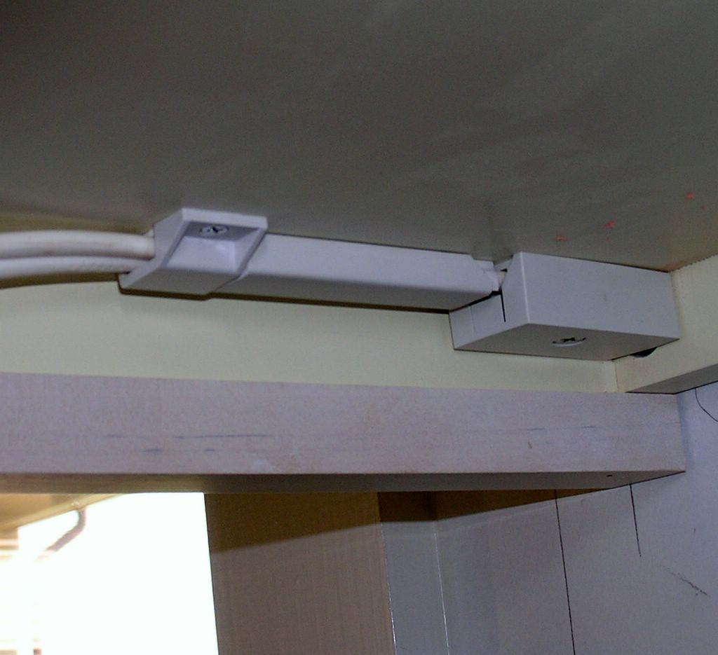
The box, with cover is shown installed. The use of double stick tape and a one hole clip secure this set-up to the cabinet. When twisting the cable to make it fit into the track, it puts added stress on the other components, necessitating a secondary means of adhesion. There is also a short piece of track cover in use here, to further secure the cable in the track base.
posted by David @ 4:19 PM
![]()
![]()
0 Comments:
Post a Comment
<< Home