June 28, 2005

Residential Electrical Design

I have been asked to perform a function, by a nationally known LLC, that is to design the electrical systems for newly designed homes, such as is required by many municipalities for the sole purpose acquiring a town, city or state building permit. I wonder if there isn't a portion of those in the home-building business who could use this service from time to time. Being an electrical contractor in the residential market, I know that the bidding electrician often gets a set of plans without any electrical design at all. Therefore, he not only gets to bid the work, but he also has to design it as he goes; how else can he do the take off and bid the work properly? What if his tastes are too cheap for this client - or too expensive - the job is awarded to another?

Being a Licensed Master Electrician, in Massachusetts especially, is the next best thing to possessing an engineering degree in my trade. But, being that a Professional Engineer doesn't usually get involved with residential electrical design, this leaves a chink in the system, through which many an electrician (a homebuilder and a homeowner or two) has been fatally wounded. Worried that you will end up with a lousy switching system that cannot be altered without a major renovation, a lighting scheme that leaves you in the dark?
Versed in the uses of many electrical products and the specification and installation of the same, drawing up Electrical-Plans for clients has been the mainstay of my business and it still appeals to me. An On-Line Residential Electrical Design Service, guaranteed to pass National Electrical Code, and pass inspection! By allowing the electricians and electrical contractors to bid from the same e-plan, you would get uniform bidding from your sub-contractors, apples to apples, oranges to oranges; consistently.

IAUL, Episode 4

The Ambiance system can be adapted to many different uses, but the most commonly used area is in the kitchen. With all of the accessories available for this system, the functions are many and varied, various and sundry (read: lots).
There are other undercabinet lighting systems out there, including small rope lighting and even neon lighting, but none as adaptable and easy to install as the Ambiance system by Sea Gull Lighting, there is a link on the page to the company's website, check it out.

When I install these fixtures in a new dwelling, the room must be rough-wired with the use of the system in mind. Since the Ambiance is a low voltage (NEC definition of low voltage: operating at 50 volts or less) system, a few things must be considered and decided upon in advance.
First off, the light feed, from either a single pole or 3-way switching system does not feed directly into the fixture, as is normally done. The line voltage (120 volts) must be fed to the line side (primary) of a transformer, to be (what else?) TRANSFORMED into 12 volts! This transformer is called a step-down transformer, since the input (primary) voltage is higher than the output (secondary) voltage. A step-up transformer does the opposite, the primary (input) voltage is stepped-up, or increased in the secondary (output).
That said, the circuit is wired so that the switched conductor, or light feed, is run to a remote location where a transformer could be mounted. I say remote, since the transformer will be installed in a convenient location, but out of sight and in a well ventilated space (read: not in a confined clothes closet).
For undercabinet lighting systems it makes sense to put the transformer under the kitchen sink where it will always be accessible and servicable. The transformer could be mounted on the cabinet back wall, or other suitably accessible location. The line (120 volt) leads are entered into a suitable junction box, usually a 4" square box, and the load leads, or cables to the light system, are entered into a separate junction box. The transformer can be mounted to the board or mounting surface in between the two junction boxes. The line voltage leads (black and white) are fed into one box, for connection to 120 volts, and the load lead conductors (since polarity is not an issue) are usually the of same color, and connect to the leads (14/3 romex) from the undercabinet.
Also available for these systems is a self-contained transformer where a junction box is included. The low voltage conductors (50 volts or less) must be kept separate from the line voltage (120 volts) by means of an isolating divider between the two voltage sections of the junction box.
When we rough in the wiring for the self-built light fixtures, the only thing we can do is vamp the wiring between the undercabinet location and the transformer location. We use 14/3 romex for this purpose. The cable ends are to be poked out of the wall and routed through the cabinet back and under the bottom shelf of the upper cabinet. Usually there is an extension of the back of the cabinet, or a portion of the frame, that extends down below the cabinet's bottom shelf. This is the recess that we will use to hide the fixture.
In some cases, where the cabinet door is the only member to close off this space under the cabinet shelf; if the cabinet door fits flush against the shelf and when it is opened you can look under and see the shelves' front edge. In this event, a second member must be installed to which the trac base will be held and adhered to the undersides of the cabinet, a trim piece can be used, or a matching wood member is all that is needed.
When we are complete with the rough in wiring, we will have 14/3 cables coming out of the walls where the upper cabinets will be installed. When roughing in the idea is to shoot for a corner of one of the upper cabinets, where the track light will begin along and behind the front edge of the cabinet.

The small junction box is where we make the transition from romex to Ambiance undercabinet cable. It consists of two barrel splices, with two set-screws on each for connection of the # 10 AWG Ambiance cable and the 14/3 romex cable. The # 10 conductor will fit into the barrel, even though it looks tough. The 14/3 is stripped of it's outer jacket and the leads are cut and stripped to fit inside the box's confines. The black and red conductors are placed side by each under the same set screw, in the same barrel splice, thus two conductors become one and the extra conductor cross-section girth helps to eliminate voltage drop by up-sizing the effective ampacity of the cable. The ground (bare) conductor and the white (grounded) or neutral conductor are likewise paired under the set screws in the second barrel and tightened fast. The cover screw is the mounting screw for the box and also a keeper for the cover itself.
From the switching system we run the 120 volt switch leg, or load side, to the separate junction box under the sink base. The line side is connected to the 120 volt leads, the load side to the 12 volt 2-conductor Ambiance cable. For this system to work properly Sea Gull lighting recommends the useof their own transformer, doing otherwise (using another transformer manufacturer) may void the warranty on the Ambiance system.
The Ambiance system is viewed best at night, and a dimmer can be used to add further ambiance to the room. Caution, a low voltage dimmer must be used to dim low voltage loads, check with the manufacturer of the transformer. Enjoy!

June 23, 2005

IAUL, Episode 3

The Ambiance installation I will use for this "episode" is one I did in my workshop, where I have set up my digital camera and tripod to take the various photos for use in this blog, I use it as a shadow box.
After measuring and cutting the 48" track section to fit in between the sides of the cabinet, I snap a 1-hole clip over the track section about 1" in from the edge of the cabinet. I then apply double stick tape to the back of the cut piece. Using as the clips as guides, I adhere the track to the underside of my cabinet with the clips flush with the cabinet face. I can use as few as two or as many as six clips snapped on to the track, for use as guides, if need be, do whatever is easiest for you. Keep in mind that you will have to un-snap each clip at some point, to insert the Ambiance cable, but you can also slide these clips along the track if need be to get them out of the way. Anyway.. You can see that I have cut a 45 degree miter (sort of, roughly) where the track meets the inside of the cabinet and joins with a vertical piece, also cut at (woof) 45 degrees; don't worry, it's under the cabinet where no-one can see it except you! The vertical side track is also adhered to the side of the cabinet with the double stick tape.

Peeling the backing tape off as you go, align the track section against the style and press it hard against the cabinet surface for full adhesion. In some case the tape will have to be supplemented with a 1-hole clip, permanently mounted in place.
Once the track system is complete the Ambiance cable can be persuaded into the track base. If you intend on using the segmented cable markings, this is the time to line them up as you wish.


The cable should snap tightly into base and pushed into the corners with an insulated tool handle, in this case the insulated grip of my diagonal cutting pliers, or dykes. Pushing the cable into the corner in this manner is necessary especially when using the track cover piece, in order to make a crisp 90 degree turn, be extra careful not to damage the cable in any way.

If desired, the cover for the track can be cut with a power mitersaw and made to fit perfectly. This is a good idea in places where the undercabinet can be seen from another part of the room and the installation wants to be neat and clean. If each cover pieces are cut to the exact length necessary the individual sockets can be snapped to the track base, fit tight to the track cover on each side, and thus they are automatically spaced in exact increments . This takes careful measuring and cutting to pull off, but it is possible to do.


Pushing the lamp socket over the cable within the track the socket should be pressed down firmly until the unit seats and a snap is heard. This is to ensure a good connection. Be careful of those points, they are very sharp!
For the purpose of greater clarity, in this installation you will see the sockets and lamps from the front of the cabinet face, I will attach a cabinet rail later on which will hide these items.
Under normal circumstances, these items would be assembled behind the bottom rail of the cabinet door, while you were standing on your head, a lot like putting a radio in a '57 Chevy's dashboard! It should be clear that anything you can do before-hand to eliminate any space-time delirium while inverted, confusing left from right, up from down; that kind of thing, is very helpful. Unless you're a tree dweller!

Notice the socket has a reflector which must reflect the lamp's light back into the cabinet, don't put these in backwards, or the light would be reflected back at the cabinet rail.
For all intents and purposes, this installation will demonstrate how a china cabinet can be side-lit with this system, or a bookcase, stereo cabinet, etc.. Do you have trouble reading the label on a CD? Add Ambiance lighting to the CD cabinet and illuminate it!

These products are from Wiremold, a surface raceway system sometimes used in conjunction with the Ambinace system.
A functioning system actually roughed in by myself at another location, is presented here to illustrate a slightly different installation requirement.

the junction box, trac base, cable and a 1-hole clip are installed under a cabinet. The junction box, or splice box, is installed here to change over from a 14/3 romex cable, to Ambiance cable.
This photo shows how the trac can be bent around corners, a unique lighting scheme indeed.

June 21, 2005

IAUL, Episode 2

The Ambiance lighting system is a low voltage application, in that the voltage feeding the lamps is 12 volts. Lighting can be designed for virtually any voltage (literally, too), however, normal house power for lighting use in the United States is 60 cycle / 120 volts / Alternating Current (AC). The 120 volt power source is then "transformed" to 12 volts AC, and this is accomplished through the use of, you guessed it, a Transformer!
A transformer you ask, what is that? A long story I don't want to bore you with, so the short of it is thus: A transformer is an electrical device that consists of two coils of wire, each with two "phase" conductors, or, at this juncture, simply two connection points or terminals.
A set of these phase conductors would be labled the input, or primary coil and the other the output, or secondary coil. As I obey the rules of basic electricity whilst building this device, I place the two "coils", primary and secondary in close proximity to one another, say like a pair of water wheels, side by side, immersed in a river of water.
This first coil, or water wheel, is energized (the wheel caused to move) by an infeed of electrical energy (read: water) filling successive buckets at the top of the wheel's motion, with gravity doing the rest of the work by dragging the wheel along with it as each filled and weighted bucket wends it's way to earth again @ 1-gravity.
The second wheel is without water filling it's buckets, but due to the movement of the first wheel and the current it stirs in the swirling water it rides in, the second wheel is pulled along with the first, in the same direction, perhaps with a little less energy than the original.
The first coil of wire, or waterwheel, is energized by an electrical current and a magnetic field is produced around it. If a second coil is in the same pool of weater (read: in the magnetic field of the first coil) then it, too will produce a current flow (read: wheel movement) in the second coil, perhaps with a little less energy than the original.
Enter Electrical Engineer with notebook, pencil and calculator, adjust figures to accommodate for losses in secondary coil by adjusting wire size in the coils of the primary coil. Eventually produce a "transformer" that converts the 120 volts of electrical energy we feed into the primary coil into 12 volts available at the secondary coil. Well, if you are not confused now, you will be shortly.....
So, our system uses these step-down transformers to produce the 12 volts necessary to energize the light bulbs.
I will start by identifiying the various system parts for you, and, along with photos of an actual installation, guide you through the process.

These are the individual lamp sockets for the system, the lamp installs in between the two posts in the front view (l), while you can see the two "spears" that pierce the cable and make electrical contact in the rear view. Trust me, these are very sharp and will cut your skin just as easily as it slices into the cable jacket (r).

This next view (below) shows the 2-conductor cable, inside the track assembly. The socket, shown snapped over the track section, actually helps to hold the cable in place, eliminating the need for the cover in this particular installation.
In this view notice the cable is marked in 2" intervals. The warning of using the wrong lamp in the system should be heeded also, overheating can cause fires; which is the result of using incorrectly sized lamps.

In this photo you can see the junction box, Sea Gull # 9459-15, this item is used in installations where the cable from the transformer to the track is run in a different cable type, in this case I used a piece of 14/3 non-metallic cable (romex). The splice allows me to change from one cable type to another; keeping the splice hidden behind a cover. When doing this, I consider the red and black, together as one phase; the neutral and the bare ground wire as the second phase. This allows for the use of the larger, combined conductor size of the two # 14 AWG, which can span greater distances without losing power.

The double-stick tape (sticky both sides) is very useful for fastening the track to the cabinet, but it must sometimes be supplemented with a clip, such as this use shown here.

The box, with cover is shown installed. The use of double stick tape and a one hole clip secure this set-up to the cabinet. When twisting the cable to make it fit into the track, it puts added stress on the other components, necessitating a secondary means of adhesion. There is also a short piece of track cover in use here, to further secure the cable in the track base.

June 18, 2005

Installing Ambiance Undercabinet Lighting (IAUL)


The Ambiance undercabinet lighting components shown here are actually the parts of the undercabinet "fixture" that you will custom build in-place, in your own kitchen.
As mentioned previously, the components of the "fixture" are the transformer, trac base, trac cover, 2-conductor cable, light sockets, lamps, clips that hold the trac in place, as well as double-stick tape.

June 16, 2005

Ambiance Undercabinet Lighting


The Ambiance Effect

Undercabinet lighting in a kitchen can be a very effective means to light the countertop workspace. Over the past several years (13) I have been utilizing an application of undercabinet lighting system called "Ambiance", manufactured by Sea Gull Lighting; with fantastic results. I say an application of the Ambiance system, because there are many different products in the line, adaptable for a great number of uses. I will be take you through an installation of one of the systems, including track, cable, sockets, lamps and transformers, and I will be talking strictly about the undercabinet installation application amd considerations.The Ambiance system consists of a flexible nonmetallic base trac, two wire low voltage cable, sockets that stab into the cable and snap on the track, a track cover piece and a transformer to drop the voltage from 120 volt line voltage to the 12 volts necessary to power the lamps.The flexible track section is predrilled along it's length at six inch increments for fastening with flat head wood screws to the underside of the kitchen cabinet. This 48" trac section can be screwed in place, as mentioned, it can be adhered with two-sided tape, held in place with snap-on 1-hole clips, or a combination of all three.The Ambiance cable, a flexible cord with two #10 AWG stranded conductors, is designed to snap into the base track and is held in place by friction, the lamp sockets and/or the snap-on track cover.The Ambiance sockets snap onto the trac while simultaneously two very sharp angled points pierce the insulated conductors in the cable and make contact. A zenon lamp, 5 or 10 watts apiece, of very white high intensity lamp designed for the socket being used, is snapped in place. The Ambiance trac cover can be used (or not) to hold the conductors in place, or to neaten up the work. The sockets are placed at whatever distance apart that is necessary, and in this way I will actually build the lighting fixture in-place, customizing each installation as I go.

June 11, 2005

Clean Clothes and Cooked Food

Clean Clothes and Cooked Food

The Laundry

Since both the clothes dryer and the cooking range in our house are electric, we must run cable to these two major electric appliances. For the Electric Clothes Dryer, which utilizes a 30 amp, 120/240 volt 4-wire receptacle, we use 10/3 romex. Size 10/3 romex is a cable assembly which consists of four conductors, all # 10 American Wire Gauge (AWG); with an insulated black and a red, considered current- carrying conductors, an insulated white, or neutral conductor (the ground-ed conductor) and a bare (no insulation) ground-ing conductor, called an equipment ground, to properly ground the circuit or device.
This 10/3 cable is pulled in between the electrical panelboard in the back hall to the dryer receptacle. With the washing machine and clothes dryer inside the closet, adjacent to the panelboard, this isn’t a very long pull. The cable is run into usually a 2-gang switch box, mounted around 36" above the floor, or so as to best serve the appliance. When the appliance is set in place, a proper 30 amp 4-wire cord must be used to bring the two live conductors, the neutral, ground-ed conductor and the ground-ing or equipment ground conductor to the appliance.

Cooking for Starters

The Electric Range requires a heavier cable than the Clothes Dryer, and utilizes a 50 amp, 120/240 volt 4-wire receptacle. This is served to the appliance with an 8/3 romex cable, which like the 10/3 cable has four conductors, in this case all # 8 AWG. An insulated red and black, or current-carrying conductors, an insulated white, neutral conductor, ground-ed conductor and a ground-ing conductor, to properly ground, in this case the receptacle and subsequently the range itself.
The range cable, as it is called at this point, requires the use of larger staples to fasten it to the studs and joists and the connectors are larger where this cable terminates in a deep 4-11/16" square steel box.
It utilizes a 4-wire receptacle mounted on a raised box cover and fastened so it stands proud of the wall by the depth of the box itself (2-1/8") plus the raised cover (½") and device (1/8") and the 50 amp 4-wire cord and cap (5/8"). This assembly must be mounted so that the appliance can be plugged into the receptacle and the range itself located such that the two don’t compete with each other for space, you’ll want to make sure there is a void at the back of the range to accommodate the depth of this assembly.

Electric Clothes Dryer and Range, 4-wire Cordsets
Another way to accomplish the range receptacle installation is to mount a 4-wire 50 ampere surface mount self-contained receptacle, these are available for the 30 amp clothes dryer receptacle and the 50 amp electric range receptacle. Like the electric dryer receptacle, where the box is mounted inside the wall cavity, the same installation technique can be applied.

Clamping for Lack of Mobility

I will mention here that all cables entering electrical boxes; most especially steel electrical boxes, per NEC must be installed in an approved connector with a clamp and two screws to tighten down and hold fast the cable in the connector. In some cases, where the connector is larger than 3/4", a non-metallic bushing is required to further protect the cable from the chafing effects caused from a cable left loosely in the connector. The point here is that, if there is a sharp steel edge against which the cable assembly scratches, there will be physical damage inflicted upon the cable sheath and eventually cutting through the insulation and eventually (and inevitably) causing a short circuit.

A Little Vibration

I should mention that I have encountered some of these cables left in loosed connectors and found in some cases that vibration has done most of the damage. What vibration? Consider that a large truck, driving by your house, cause a rumble in the earth that you can feel, applying these same factors to the electrical box situation, you can see the problem is a very real one.

Home Runs Without Rounding the Bases

The home-run cables are all brought to the main panelboard for connection to the power source, through the eventual use of circuit breakers. Each cable must be run through an approved two-screw connector and, if the connector is 3/4" or larger, we also need to install a non-metallic bushing, over the end threads of the connector to protect the cable from chafing damage. The reason that smaller cables don’t require non-metallic bushings? The larger cables are much stiffer and weigh more and thus more damage is done to the cable insulation when pressed against a sharp steel edge.

Various 2-Screw Cable Connectors, Note Blue Plastic Bushings on Size 3/4" Connectors and Larger.
Once inside the panelboard, the individual conductors of the cables are separated from each other and connected to the various electrical busses. An electrical buss is basically a terminal strip, or a common place to terminate the various sized conductors, held tightly in place under set-screws.

Public Transportation It is Not

A Ground Buss is a terminal strip for the ground-ing conductors. Bare copper; sometimes with green insulation; sometimes green and yellow striped. Solid copper or stranded conductors each one is placed under a set screw and tightened down fast. Assuring the screws are turned in tight is essential to electrical safety, a loose connection causes a voltage drop, as the current flow soars conversely, overheating and arcing, or sparks caused from the “chatter” of the loose connection. This condition is the number one cause of electrical fires, through-out the world. More on that later.
A Neutral Buss is a terminal strip for the ground-ed, or neutral conductors of the 120/240 volt system. I do not understand why they do this, but the NEC does not use the term “Neutral” for the Ground-ed conductor, they simply refer to this conductor as the Gound-ed conductor. This simple lack of definition cause a great deal of confusion, even for the veterans (like me) who skim the text of a dog eared Code Book and find themselves confusing the two terms. Anyway, the neutral conductors are individually connected to the terminal strip with a single conductor, solid or stranded, each under it’s own single set-screw.

Power Please

The remainder of the conductors are the power connections to the individual circuit breakers within the panelboard. Each “circuit” has it’s own characteristics, as I have mentioned before, with each conductor size warranting it’s own properly-sized circuit breaker (over-current) device. A # 14 conductor is protected at 15 amps; #12 at 20 amps; a #10 at 30 amps, and a 38 at 50 amps, etc., etc.. Over fusing is another area that causes a great deal of confusion also, not to mention fires, but this time it is not the electrician that is mistaken, for he knows better. This time it is the unaware homeowner that does the deed (overfuses) and cause an unsafe condition, - overheated conductors causing insulation failure, or worse, and eventually a very hazardous situation for the occupants of the house.
A 120 volt circuit, having it’s white and ground conductors connected to the neutral and ground buss, is powered by a properly sized single-pole circuit breaker. A 240 volt circuit, such as the electric range and the electric dryer we have in our house, is powered by a properly sized double-pole circuit breaker. At this stage of the job, the rough in, we are not installing circuit breakers, that will come later.

The panelboard must be covered to protect it during the construction period to keep contaminants (construction debris and water) from damaging the electrical connections and components.
We will be installing the service to this house soon, stay with us......

May 15, 2005

Rough Wiring Continued

Two Wire Cables

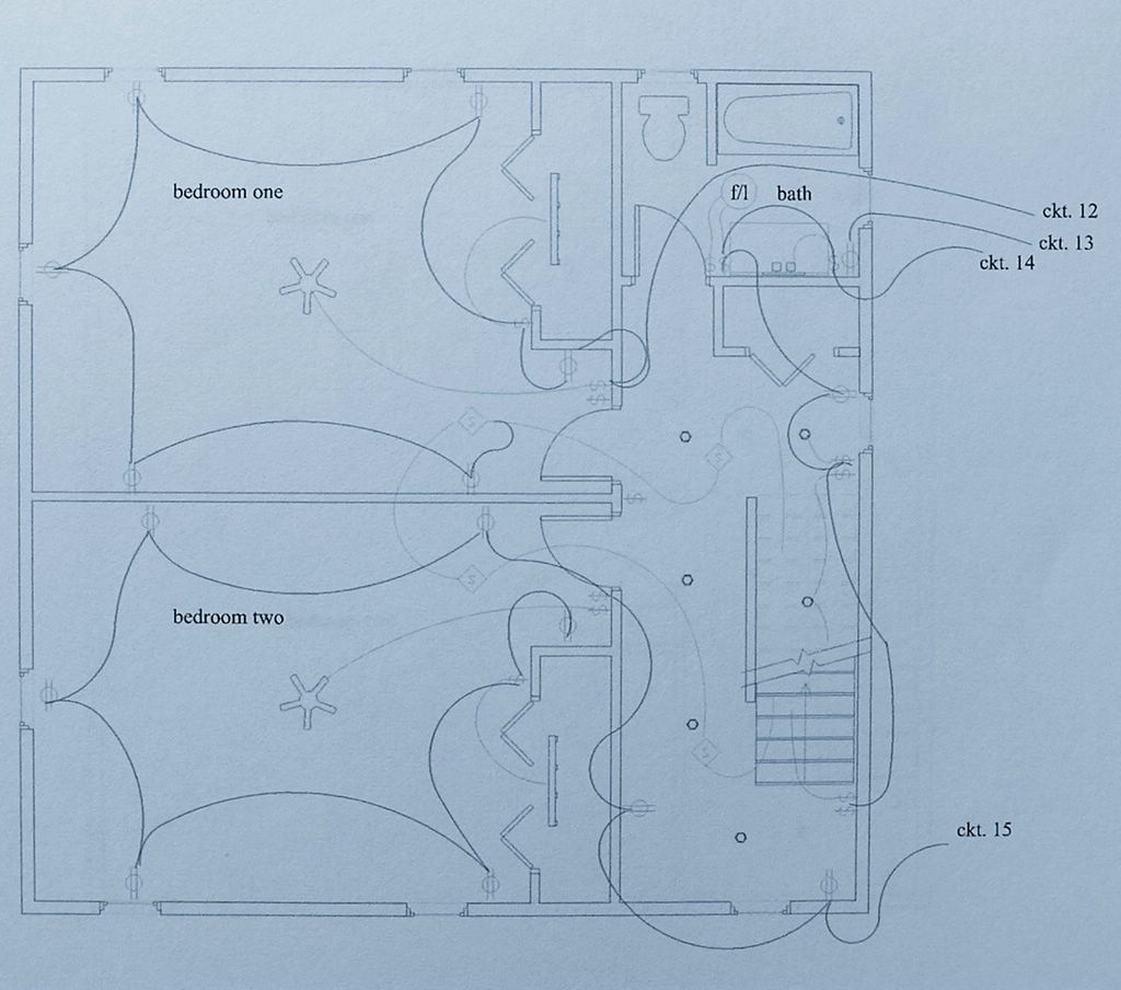
After the 3-wire (14/3) cables are pulled in to the various 3-way and 4-way switches, I begin with the circuit feeds and interconnecting 2-wire (14/2) cables in the circuits, running between the devices in each room. Again as you can see from the 2nd floor electrical plan, the circuits themselves contain up to nine items, or utilizations. A utilization is a place where electricity is consumed by an electrical load of some sort, a light fixture, a ceiling fan, or simply a table lamp plugged into a receptacle are examples.

Circuitry Simplified


Again, if you follow the circuitry around the 2nd floor rooms, you will see that circuit # 14 picks up the vanity light, the fan and light unit in the bathroom, then it runs to the receptacle under the window in the hall, to the 2-gang switch at the top of the stairs, where it feeds the hallway recessed lighting (note lighter circuit line from 2-gang switch to the first fixture in the hallway array).
The same 14/2 cable is then run to the front of the house, where it feeds the 2-gang box at the base of the attic stairs. This makes nine uses, or utilizations, on that particular circuit.
Circuit # 15 feeds the two receptacles in the hallway, then the ceiling fan in bedroom two, where the cable is run to the 2-gang switch just inside the bedroom door. Notice the lighter cable from the switch location to the ceiling fan, this is how the fan would actually be fed, from the switch to the fan unit. If you also notice that there is no wire depicted any longer from the 2nd switch in that 2-gang location and doesn’t have a lighter circuit line leading to an outlet or another switched device.
The reason for this is that the other plan depicted the switching arrangement, not the circuitry, the difference you ask? Simple, if you follow the lighter circuitry line from that same 2-gang box to the first receptacle, on the adjoining wall to bedroom one, you will see that it continues around the whole room and ends up feeding the switch for the closet light. Keep in mind that these are circuit lines only, and they only tell you half of the story regarding the method we use to make things work.
In every receptacle and switch box there must be at least one cable to utilize when connecting a device, this cable containing the required conductors for the use intended.

Line and Load Conductors

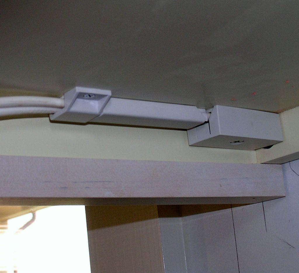
We have discussed using 3-wire (14/3) cable between the 3-Way and 4-Way switches, and between the smoke detectors. We haven’t discuss the other uses for this same cable; that is to carry live power and a second switched conductor within the same cable assembly.
Going to the first receptacle on the adjoining wall to bedroom once again and consider the cable (again) that runs back to the 2-gang switch box at the door. If we use a 3-wire cable (14/3) in this cable run, instead of a 14/2, we could bring to that location a constant feed conductor and a switched conductor . We could then continue to the next receptacle in bedroom two, on the same wall, with the 14/3 cable. In so doing we are able to switch those two bedroom receptacles (actually half-switched) and provide continuity for the un-switched conductor to continue around the room and activate the other devices and light fixtures.
Multiwire Branch Circuits
A third use for 14/3 romex, or any three wire non-metallic (NM) cable is to bring two separate circuits to the same location, each of theses two circuits would use the same white, or neutral conductor. Without getting too technical here, suffice it to say that the single white conductor, feeding both circuits, only carries the unbalanced load of the circuit. Un-balanced load? What does that mean?
Well, I should explain this for you in finer detail, especially since I haven’t even mentioned, as of yet, what a balanced load is, so here goes.
Balanced or Unbalanced?
A balanced load would be a circuit where the electrical load (amperes) is equal in both conductors of a 120/240 volt, three wire circuit, and where no current at all would flow in the neutral conductor. In this manner the circuit is just exactly that, a complete path for electrons to flow in a complete lap from start to finish. This balanced load would then be acting as a series circuit, using the neutral conductor of the three wire cable to complete the "circuit", when actually it is a connection, on the neutral buss inside the panelboard that accomplishes that. The circuit would be made without drawing current from the neutral buss at all, as long as the load amperage was matched evenly on each individual conductor.
If the circuit were to become un-balanced, such as what would occur if turning off a part of that electrical load, like a single light bulb, the neutral, or white conductor, would then carry that un-balanced portion of the current. In any case the neutral will never be subject to overload, as long as the three wire circuit was connected properly at the panelboard. More on that later.

240 Volts and Cable Assemblies

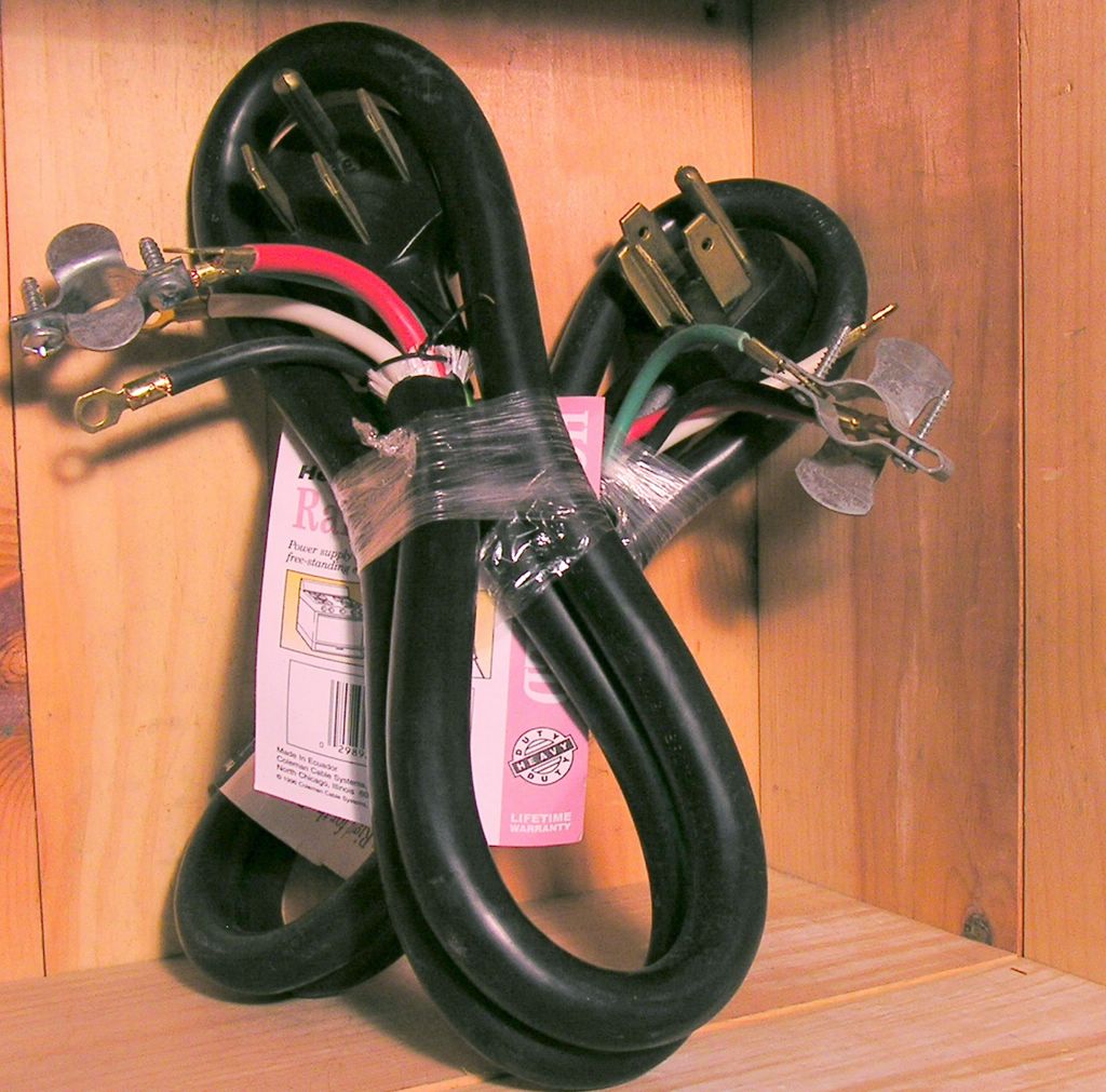
To dispel a myth, although most people think you must have large cable to carry 240 volts, as if 240 volts was somehow bigger than 115 volts, this is not true, all NM sheathed cable, from 14/2 romex and up is rated for 300 volts, maximum between conductors. Large cable, with large conductors, can carry more amperage than cable with smaller conductors. This larger cable is used usually to feed an electric dryer, or electric range, where the amperage is between thirty and fifty amperes, and they both use 240 volts. Conclusion, large conductors - more amperage, small conductors - low amperage; conductor size is not a consideration when used to carry 240 volts, conductor size relates to amperage capacity of conductors in the various cable assemblies.
Home Run Is Not Just Another Baseball Term
As we near the end of the rough-in portion of this house, and before we are finished running power and lighting cables, we must install the home runs, or circuit feeds to each of these circuits. From the plan, we have circuits # 12, 14 and 15, all 14/2 cables, that must be brought down to the panelboard location, and, in this case, the main electric service equipment. Remember that the circuit feeding the bathroom outlet, # 13, must be a separate 20 amp circuit to meet NEC, so circuit it is run in 12/2 romex, to handle the higher amperage (20 amp).
Location Of Service Equipment
At some point during the siting of the house, the location of electric service to the building will have been decided upon. Factors that affect this process are then considered, the first being each particular building site and the source of electric power. Is the electric power delivered overhead on poles, or underground in trenches including the conduits, if required? Usually the decision is made to go to a particular pole, or underground connection box or transformer. Usually, but not always, the distance is the major consideration and the cost the motivating force.
Although the sight of an electric meter on the side of the house facing the street isn’t the prettiest of things, the sight of the overhead cables for cable television, telephone and power are even less inviting a sight! Therefore, asthetics does play a role in some situations. But I don’t want to wander too far off-station when I just wanted to locate the service equipment in this particular house. Once we locate the panelboard, this is to where we pull all of the cables, or home runs, from each individual branch circuit.
Knowing the panelboard location, the electrician would then determine the best route for all of these home runs. Usually a series of holes are bored above the location, in this case the service panelboard is located in the back hall, in the closet partition, facing into the hallway.

Busy Spot That Kitchen!

Another consideration when determining the panelboard location is the proximity to the major loads. In this case the laundry, with washer and dryer are right there in the closet behind the panel location, also, the kitchen, with the various appliances and appliance circuits, is also close by. This is considered a great spot for the panel, especially in regard to cabling for the much busier kitchen area, circuits-wise (six circuits total) than any other part of the residence.
All this said, the electrician now has a "home" to go to for power for each of the individual branch circuits. From the drawing of the first floor you can see circuits #8 through #11, circuit #6 is the homerun for the required 20 amp GFCI protected receptacle at the bathroom vanity.

Telephony and Cable TV

Once the 14/2 circuits are installed, and the kitchen appliance, 12/2 or 20 amp circuits, are also pulled in to their respective locations, the cutting in and splicing of all of the cables into all of the electrical switch boxes can commence. While the electricians are doing that, I will explain the next cabling jobs we do in the home.
In 1982 or so, back when a telephone system monopoly existed in the United States, laws were passed to de-regulate the telecommunications industry, or Ma Bell - as the amalgamation - American Telegraph & Telephone was called at the time. The de-regulation itself caused a shift in policy at the old AT&T, whereas the phone workers no longer did the cabling inside the home for a new customer.

More Work For The Electricians

This work was left to us, the electricians, to perform the task of installing telephones in homes and businesses, as a part of our services. We now do all of the interior telephone system installations and the telephone company only brings the dial tone to the interface on the side of your home. This was a sort of boon for electrical contractors, but the benefit to the consumer was short-lived, as companies re-structured and got around the monopoly policies of the new system.
Today we have the same monopolies, but the telephone workers themselves are increasingly harder to find. Downsizing has caused a lot of union telephone workers, from the International Brotherhood of Electrical Workers (IBEW) to lose their jobs, oh well!

Cable Television Went The De-Regulation Route Too.

This same downsizing and restructuring has had the same effect in the cable television industry, whereas the electricians now do the in home installations, the Cable TV companies simply provide a place to connect our in-house TV system of splitters and cables and sometimes signal amplifiers for the larger installations.
That said, the cables for the telephone are now installed in the dwelling.
In the second floor bedrooms you can see the locations for the telephone, on what will be the bed wall, and the cable television outlet is across the room. Makes sense right? The phone is near you and the television is across the room?
Each telephone location is fed from the main telephone lines, called an interface, usually installed on the outside of the house, ultimately near where the power will enter the building. Each telephone has a single cable from each location to the interface, the telephone cable I have been using for twelve years is known as Category 5e. This cable assembly consists of four twisted pairs of wires, which allows the connection of up to four lines, such as a home line, a business line, a fax line, and an internet-connection line, if necessary. These "pairs" are twisted around each other at different rates, say five twists to the foot, then four twists, etc., to eliminate cross-talk between pairs. Cross-talk is the ability to hear the conversation, or conversations, of other users, on the different pairs of un-twisted conductors.
This is also true for the cable television cables, where they, too are connected to an "interface", supplied by the service provider. Each television location is separately cabled back to the interface, where the Cable TV guys hook up our system of splitters and amplifiers.

April 27, 2005

Rough Wiring, Continued

Pulling Cables

So, with the holes all bored out in the studs, plates and shoes of the walls, it is time to actually pull in some wire. Again, on the second floor, the various cable assemblies (e.g.: 14/2, 14/3) are "run out" to speed the installation time, as well as to keep the cables from twisting as we pull them through the bored holes. This is a process that can be simplified by buying an uncoiling device, such as the one in the photo, a sort of lazy susan on which the coil of non-metallic sheathed cable is placed. The cable is then threaded through the outplay arm, or bailer, to avoid tangling. The unit itself is held in place by a friction connection of two steel arms which straddle the wood framing members; actually designed for use with the vertical 2 X 4 framing studs, see photo.


While the unit splays out the cable as you pull it, the spinning motion uncoils the wire just as it was manufactured (actually in the reverse), flat, kink free, and ready for stapling neatly along the framing members. Keeping the wire straight in this manner simplifies the installation, and keeping the wire straight is a much easier task than making it straight again once you’ve tied it in a square knot! I have been asked how I am able to do such a neat job of cabling and stapling; the answer is always the same, don’t foul the line and it won’t ever need untangling. (A bit of maritime humor here, I come from a long line of fisherman, beginning in 1848, in Gloucester, Massachusetts).
Beginning with the 14/3 cable, I will pull in the 3-way wiring for the 2nd floor hallway lighting. I drag a cable up through the bored hole above the 2-gang switch box at the end of the hallway, at the base of the stairs to the attic. Pulling across the top plate of the framed 2 X 4 wall, the cable is kept inside the framing members, woven under the ceiling joists and between the furring strips of the ceiling construction. Once the cable is pulled across the hallway, it is then routed in a manner parallel to the joists, above the furring strips, to the area above the electrical box for a 4-Way switch. The 4-Way switch, which is part of the upper hall switching system, is located between the two bedroom doors. It is then pushed down through the bored hole above the switch box, gathering enough wire to reach the switch box, plus an extra 12 - 14" of slack. To prevent pull back of the cable it is stapled to the wood stud, just below ceiling height. The cable is then neatly stapled parallel along the ceiling joist until it reaches the crossing point in the hallway. It is then stapled across the underside of the joists, to the location above the initial 3-Way switch. The cable can then be pulled back taut and cut to length, leaving 12 - 14" of extra cable.
This done, a second 14/3 is pushed up through the bored hole above the same 4-Way switch and it is led down the hallway, over the furring strips toward the bathroom, until it reaches a point across the hallway from the 2-Gang switch box. From there it is woven under the ceiling joists and pulled down through on of the bored holes in the wall plate above it. Leaving the appropriate amount of slack, the cable is then cut off and it is stapled back to the stud, again just below the ceiling level, to prevent pull back. Stapling the cable to the underside of the ceiling joists, the cable pulled taut as I go across the hallway, for neatness. I finish stapling the cable parallel to the joists down the hall and back to the 4-Way switch box. These cable staples are the insulated variety, so as not to damage the cable. These are staples we are driving here, not railroad spikes, we don’t drive them in so far that they cut into the cable (I’ve seen apprentices do this).
I am not going to demonstrate the installation of each cable in this way, but you get the idea that this is the way to run cable, parallel to the framing members where possible, following the contour of the object being traversed, crossing at right angles otherwise. Always follow this method, keeping the cables parallel to the members and stapled back, away from the finished surface by 1-1/4", per NEC rules. For cabling in basements, running across ceiling joists is limited to # 6 AWG or larger (the smallest allowable size / conductors in the cable).

If I show you the 2nd floor circuit layout, you can see how we might feed the various devices.


The single, darker lines between items depicts a 14/2 cable, as it enters, and sometimes also leaves each electrical box, at every duplex receptacle location, as well as some of the switch boxes. No, these items are not wired like the old Christmas tree lights - where if one lamp goes out - they all go out, that would be a series circuit. These various electrical load devices (light bulbs in lamps plugged into wall receptacles) are wired in parallel, but they are none the less on the same circuit! If the circuit breaker trips, or if a fuse blows, the entire circuit will go off (eight or ten electrical items) and nothing on that particular circuit will function.

Trouble Shooting With Ease


A key factor to understand and consider when doing your own electrical system work, and that is the fact that every wire, connection or device is part of a larger schematic diagram. Therefore if any of these elements fail to perform, the electrician may have to search through every electrical box, checking splices and such - while trying to troubleshoot, and therefore it sometimes does take some time to determine the source any problem. Believe me, for a professional like myself, finding trouble in a circuit that has been tampered with, either by the homeowner or an otherwise inexperienced person, is up there with the most time consuming and frustrating of endeavors! Nothing that the novice has done makes any sense to the pro, not the order, the method or the end result.


Existing Electric Wiring & Remodeling Or Renovation


You should consider that the licensed electrician responsible for the existing wiring in your house probably knew what he was doing and interconnected the various electrical elements according to accepted codes and practices, at least those codes that were in-force at the time of the initial installation. (most licensed electricians are well qualified, no matter how immensely unsung their feats; the least of which include hazard and intrigue) Therefore, the electrical cables running in between the studs and joist of your home, are a portion of those many circuits.


Circuits Interrupted


When a renovation project requires that a new window or a new door (or the old in a new location) be installed, a cable or series of cables might be found in the wall cavity in which the new opening is to be located. They might be serving other needs besides those in that particular room; the found cables could run to the 2nd floor, the basement, or elsewhere in the building. Interrupting the circuits (severing any cables) would cause the loss of power to all or some of the devices and/or utilizations that are a portions of any particular circuit. For this reason, remodeling or renovation electrical work is more costly than similar tasks being performed on new buildings; especially while under construction.


Feed Through Devices


duplex receptacle, traditional, showing removable tab

In a duplex receptacle location, the conductors are connected to the duplex receptacle on one set of terminal screws (black to brass & white to silver) and fed out of the receptacle on the other set of terminal screws, these receptacles are therefore connected in parallel and are known as feed-through devices. There is a "tab" connecting the two screw terminal screws to each other; break off that tab, the connection is broken, and the device ceases to feed out to the next receptacle or electrical device. We use this broken tab feature to enable a switched receptacle, and, when necessary, the feed-through feature is accomplished with a splice and pigtail.

Switches And Their Place In The Home


Switches are housed in electrical boxes from 1-Gang to 4-Gang or 5-Gang and sometimes larger. The switched loads, or lighting fixtures, can be supplied with power through a number of configurations; in the case of a 3-Way system, at the first or second 3-Way switch location, or even at the fixture itself.
Back to the 2nd Floor plan again, where circuit 14 is routed to the 2-Gang box at the vanity where it powers the vanity fixture and the 14/2 is spliced-through to the 2-Gang switch box inside the bathroom door, where it powers the fan / light unit; on to the 2-Gang switch box at the top of the stairway, where it powers the upper hallway lights, and, finally, to the 2-Gang switch box at the base of the attic stairs.
Follow circuit 12, as it first hits the 2-Gang switch box inside the door in bedroom one. In this switch box is the load wire out to the bedroom ceiling fan as well as a line wire out to the 1-Gang switch box, a load wire out to the fluorescent closet fixture, a line wire out to the bedroom receptacle, and so on.
The cables we have just pulled-in to the multitudinous switch and receptacle locations now serve as the network for the next step in wiring the building. That is entering the cables into the various boxes and connecting the circuit conductors, the switched loads, the 3-Way switch travelers, the Single Pole switch returns, the switch legs, comes right now.


A Bunch Of Spaghetti You Say?


As any good electrician should do, I have labeled the cables as I pulled them in to their sundry locations; through way too many bored holes. One at a time the cables are neatly stapled down the stud, with insulated staples, keeping the cables away from the finish side of the stud and out of harms way; kept from impalement by drywall screws, or picture-hanging nails.


Stripped Of Their Dignity


One by one, the cables are stripped of their outer jacket, untwisted and disentangled from the various nonconductive packing materials or components, and pushed in to the plastic, knock out cable entries available on plastic switch boxes. The cables are usually entered into the multi-gang switch box in the actual location where the switch is to be; that is, if the cable was for the first light in the room, the cable would enter into the 1st "box" or "ganged" location, if there were a 3-Way switch location, both cables would end up in the same box or "gang". I usually would mark the load from these switch locations to ease identifying them later. The various conductors of these cables would be spliced together, starting with the grounding conductors. In the plastic box we would have to provide a pigtail to be connected to the ground screw on the device, for grounding purposes, therefore the two copper conductors from the two cables and a third, loose conductor, suitably long for the job, are twisted together, in a clockwise direction, an appropriately sized wire nut would be threaded on and the whole thing pushed to the back of the box. The next conductors to tackle would be the neutrals, or white conductors. The whites are gathered together, and one by one they are bundled together neatly, formed so as to facilitate conforming them to the shape of the ganged switch box most efficiently. They are stripped to their proper length for splicing, twisted together, a wire nut installed and the whole thing folded back neatly into the box. The conductors that will be affixed to switch terminals are pushed aside; the remaining black, sometimes red conductors will then be spliced together in the same manner and, if need be, pigtailed for use to power a device or multiple devices. At the rough-in stage, the individual conductors are wrapped to one another, to label, or distinguish, the use of a Single Pole, 3-Way or 4-Way Switch, and pushed back into the box.


Repetition Equals Carpal Tunnel Syndrome


This method is repeated time and again, for circuit after circuit until the whole house is interconnected and ready for inspection by the Local Authority Having Jurisdiction, or, perhaps more succinct, the local Inspector Of Wires.
All of the homeruns (branch circuits)are pulled in to the location of the panelboard for connection for power.
At this time however, the rest of the cables can be routed throughout the structure, for cable television, maybe a satellite dish, telephone locations, including both desk and wall mount phones. Or, these days, maybe a network for the Personal Computer users in the house, an ethernet system for a home office, fax lines, etc., etc..

April 18, 2005

Rough Wiring Segment

The Walk Through Is Through


With the Walk-Through complete, the final layout of the electrical system can begin, even if there are a few details to iron out. At this point the rough-in wiring of the house’s electrical systems can begin.
On Your Mark, Get Set, Wire!

I always start my wiring jobs in the area the furthest away from the electrical panelboard, from which all the electrical feeders and branch circuits within the house will originate. If there is a sub-main panel board, this is where some of the branch circuits will originate; a sub-main feeder from the panelboard supplies power to it.
Remember these words "feeder" and "branch circuit", they are very important, distinctive and descriptive words. The definition of a feeder is: All circuit conductors between the service equipment, the source of the separately derived system, or other power supply source and the branch-circuit overcurrent device. The definition of a branch circuit is: The circuit conductors between the final overcurrent device protecting the circuit and the outlet(s).
There are also several types of branch circuits within a dwelling, or for that matter in any building being wired.

  • An Appliance branch circuit is one that supplies energy to one or more outlets to which appliances will be connected and has no permanently connected luminaires (light fixtures) that are not part of an appliance.
  • A General-Purpose branch circuit supplies two or more receptacles or outlets for lighting and appliances.
    An Individual branch circuit that supplies only one utilization equipment.
  • A Multi-Wire branch circuit consists of two or more ungrounded conductors that have a voltage between them, and a grounded conductor that has equal voltage between it and each ungrounded conductor of the circuit and that is connected to the neutral or grounded conductor of that system.

A large building may have a main service panelboard and a sub-main panelboard at a different location, as part of the electrical distribution system. Some of the largest buildings will have many feeders and sub-main panelboards, spread throughout the building. In this way, all of the circuits (home runs) do not have to originate in the same panelboard. Our small house, has only the main service panelboard, where each and every circuit in the building will originate.

Click On Plan To Enlarge

Bath GFCI Receptacle

Notice that Circuit # 13 feeds the GFCI receptacle in the bathroom, and per NEC will be served with 120 volts, 20 amperes. Hair dryers, curling irons, all use more electricity than your electric toothbrush charger, or an electric razor.

Bedroom Circuits And Smoke Detectors

Circuit # 12 is for receptacles and fan, as well as the closet light and receptacles in Bedroom One, but, can you also see the heavy line to the smoke detector, from that same bedroom circuit? That is the “power feed” for the detector system. This is a common way to feed the smoke alarm system, in that the fire detection system is required to be fed from a lighting circuit, instead of a circuit alone and by itself. The thinking behind this rule is, if the homeowner, tenant, or occupant wants to turn the smoke detectors off, they must also have the inconvenience of losing a lighting circuit. In this way the homeowner isn't as liable to turn the smoke detectors off and leave them off indefinitely.

So, in this case bedroom one is the master bedroom and, if circuit 12 were turned off, there would be no power in that master bedroom, no fan, no lights, no television, nothing but darkness. Get the point? In most cases the detector can be taken down by the homeowner and reset, you'll see how shortly.

Battery Back-Up

These days the smoke detectors we install are self-contained, with battery back-up, in the event of a power failure. This is an excellent way to ensure fire detection coverage even when the power is off! But, the batteries don't last forever, so if your own smoke detector in your present home is chirping at you, it is usually but not always an indication that the battery needs to be replaced.

It is always recommended that you replace all of the batteries in all of the detectors at the same time. Ergo, if one battery is dead the others can't be far behind. Local weathermen usually insist we check our smoke detectors batteries each time we toggle between Standard Time and Daylight Saving Time, in the Spring and Fall. What is that, Fall down Spring up, no, Spring forward, Fall over, or is it Fall back, Spring forward? Whatever, remember to change the batteries in your smoke detectors!


Pictured is a Firex brand smoke detector, notice the base plate, the wiring pigtail which plugs in to the back of the detector and the "bathing cap" for added protection from dust and paint during periods of construction, cute eh? The cap must be removed after the dust has settled for the unit to properly function.


smoke detector, rear view
This view of the back of the unit, which shows the battery compartment, this model number 4480, note it uses a 9 volt radio battery, the one with the male and female snaps for terminals.


Interconnected And Loud

Each of these smoke detectors has to be hard-wired together, or daisy-chained, so that they alarm in tandem with one another; so if one goes off, eventually they all will go into alarm mode and nearly shatter your eardrums at a sound level of at least 8.5 decibels, the minimum required audio level. Okay, so it won't shatter your eardrums, but it certainly will wake you up!

Re-Setting A Smoke Detector that Has Gone Into Alarm

To clear a smoke detector that is in alarm; that is not involved with a fire, simply turn off the circuit that is feeding it for several moments. Allow the smoke chamber to clear, and, via the printed circuit board, reset itself. If when the circuit is re-energized, the detectors still will not reset, it may be that one or more of them are dirty, contaminated, or simply have an insect crawling inside them (a common problem).

Placement Of Detectors

Notice the lighter lines (representing cables) connecting the smoke detectors in the bedrooms, hallway at the base of the attic stairs and on up to the attic, if a detector is required there in your town. From the light switch, there is a cable for the attic light. Note also that the other end of the smoke detector system the cable heads down the stairway to the first floor detector, mounted on the ceiling near the bottom of the stairs.

A Little Physics Lesson

It is common knowledge that hot air rises, as does the smoke from that incendiary source. Therefore the smoke detector at the ceiling of the lower level, near the base of the stairwell will be activated by the smoke wending its way to the second floor. This smoke, heated from the fire, rises to the ceiling and once there, spreads laterally across the ceiling. At the point where the ceiling meets the wall, there is what is known as a dead zone, in regard to the smoke and the now-heated ambient air. This "dead" zone doesn't allow the air currents to reach all the way into the corner, therefore it is best to mount the detectors at a minimum of 12" away from adjoining walls, and, for cathedral ceilings, three feet down from the highest point. The same law of physics applies here, in that eventually the super-heated air will fill the airspace at the roof peak, and actually block out the smoke, rendering useless a detector mounted at that level.

Cleaning Smoke Detectors

Cleaning smoke detectors is a project you, the homeowner, can do yourself. It is always best to take the detectors down one at a time. They all unscrew or twist counter-clockwise from there ceiling mount and unplug from the power source, with a safe and easy to operate plug-in mechanism. Use a vacuum cleaner to either blow or suck the dust or bugs out of the unit. Once cleaned, reconnect the plug and reinstall them as they were previously.

Once all detectors are installed, the Smoke Detectors must be tested for functionality. On the face of each detector there is a small push button for testing the detector. Pushing this test button should activate the smoke detector in your hand first; holding the button down until you can hear all of them chime in together is a simple way to ensure your family's protection from a fire. Releasing the button will allow the detectors to recover by opening up a relay in the detector itself; it may take several minutes before they are completely silent.

Fire Inspection

The building department, or fire inspector, will schedule an actual fire test, by introducing smoke directly to the smoke detector with a smoking torch. He will then check that all of the detectors are ringing, as is the code.

The electricians begin on the second floor, by first nailing all of the electrical boxes in their respective receptacle and switch locations as per the electrical plan (e-plan). From the e-plan can be identified all of the elements included, and these elements are then transcribed to the wall studs of the building, usually with a felt tip pen. The electrician would go around and mark an S1, S3or S4 on the stud closest to where each item, the switch, light or receptacle, would be mounted. Remember that we are talking about wood studs and that these are usually set at 16" on center and our 'locationing' is limited somewhat by support members that cannot be drilled through, chiseled into, or removed entirely.
Receptacles can be mounted at virtually any height, but, to comply with NEC an outlet must be mounted below 5'-6" to be considered a required receptacle. Receptacles serving the kitchen countertop, a bathroom vanity, or wet bars can be a maximum of 18" above the counter, vanity or wetbar to be the required receptacle. That said, we follow these general rules, but each individual electrician has their own mounting heights for these different units.


Hammer Height?

In new construction, I ask the guys to mount the receptacles at 14" to 16" above rough floor, or hammer-height, as long as the installer use the same hammer in each room, of each house, bar none.
Hammer-height is achieved by placing the box against the stud we are mounting the electrical box to, lining up the depth of the wall covering with the gauge that is etched on each individual box. By laying the hammer head on the floor, with the handle held vertically against the chosen stud, the box can be set atop the handle for the height. Each hammer manufacturers length varies by an inch or so, from tool to tool, but they are all roughly 14 - 15" long.
Switch boxes I like to mount at 42" above the rough floor, or 41-3/4" above the finish floor. This may vary from room to room, to accommodate special wall treatments like wainscoting, beaded paneling, or some other architectural feature that must be recognized and reconciled into the placement of these devices.
If we are doing a remodeling job, or partial renovation, I try to match the existing switch heights within the original structure. As to the receptacles, they can also be mounted in the baseboard, or mockboards, to remain unseen as they perform their function for compliance and convenience. Or, they can be mounted to match the existing detail of the building being remodeled.
Telephone, Cable TV, and Data locations can follow the receptacles and be mounted at so called hammer-height, or be in the baseboard. In the kitchen, they can be mounted at the counter top height, matching the switch height for general congruity, or you can have a wall-hung telephone, mounted at 60 or so inches above the floor, 24" above the counter top. As with most everything else these days, telephones are cordless, everyone uses answering machines, and, if you have a data line you have a PC; therefore, it is a good idea to place these data, telephone and catv outlets next to a duplex receptacle, or, in the alternative, place a duplex receptacle next to them!
After the rooms are marked out for the boxes, and the boxes are all hung, 1-gang for the receptacles, some 2-gang boxes, as well as some 3 or 4-gang boxes for the switches. The rooms are then drilled-out for the non-metallic cable (romex) that will course through, between and behind the buildings inner sanctum; the framing and finish construction components.
Usually a single hole is drilled above every single switch or receptacle box (1-gang), two holes for a double switch box (2-gang), etc. If some of the switch and outlet locations are accessible laterally, through the adjoining studs of a wall, we drill horizontally only when it makes sense to do so. No matter how the wall and ceiling members are drilled out, each hole must occupy the center of the framing member being drilled through. Also, when stapling the romex, the cable must not ever be closer to the finish side of the wall than 3/4". These rules are an effort to prevent a cable or group of cables being pierced by a nail or a drywall screw. In the case where the wire is run closer than these guidelines, a metal plate must be used, of at least a 1/16" thickness, to prevent this hazard.
Remember, that if a nail or screw pierces the cable, and doesn't trip the circuit breaker, that nail head or screw head is now electrically alive. If you were to paint over a screw that is so-energized, especially with latex, water-based paint, you would receive a small shock. I know this first hand!
The electrician and his apprentice continue to mount electrical boxes, for the various devices, switches, receptacles and light fixtures. The second floor has the recessed lights in the hallway, a fan & light unit in the bathroom, one closet fluorescent in each bedroom closet and the smoke detectors.

Click On Plan To Enlarge
Once the switch boxes, recessed lighting frames, ceiling boxes and smoke detector boxes are all mounted, and the holes are bored throughout, the electricians will then start to pull in some of the cables for the connection of the various elements that comprise the electrical system. So, as they prepare to start pull the circuits, switch legs, light returns, cabling for the smoke detectors and 3-Way light switching systems, I will explain the tasks at hand in more detail.

Before I go there though, I should explain to you the cable assemblies themselves, how they are constructed; what they are designed to do. This is a many faceted subject, that I will explain here briefly, as well as make other references and add further explanations of their make-up and uses for you, as we go along.
American Wire Gauge, or AWG, is a standard for conductor size, adopted as American Standard early in the developmental stage of wire and cable manufacturing. For all intents and purposes, we will be talking mainly about the following AWG sizes in the residential wiring sphere, I will list them by size and briefly explain the uses of each. Keep in mind that the lower the number, the thicker the AWG size and the higher the amperage they can carry. For the intention of this article, only copper conductors are being discussed, unless stated otherwise.
Starting at the bottom, from small to large:

  • Thermostat wire, or low voltage control wire, comes in both 18 and 20 gauge, with configurations of up to 8 multiple conductors. An 18 gauge, two conductor cable is expressed as 18/2; a 20 gauge, three conductor cable is expressed as 20/3, etc. Ergo, gauge / conductors. As the name implies, these cables are used for thermostats and controls such as garage door openers, doorbells and buttons, furnace wiring, zone valves and dampers, among other uses. Thermostat wire can be used for voltages up to 300 volts (between conductors), but generally in the uses mentioned they carry only 16 volts for your door chimes; or up to 24 volts for your heating or cooling thermostat.
  • Non-metallic sheathed cable (romex) is available in gauges from 14 to 2, with configurations of up to 4 multiple conductors, plus a grounding conductor. A 14 gauge, two conductor cable is expressed as 14/2 Romex; a 2 gauge, three conductor cable is expressed 2/3 Romex. Not expressed, but none the less included in the cable, is the grounding conductor. These cables can be used to wire receptacles, lights, switches, small appliances, etc., mostly used in wood frame construction.
  • Service Entrance Cable (SEU) or (SER), comes in gauges from 10 to 4/0, in configurations of up to 4 multiple conductors, and a grounding conductor. A 10 gauge, two conductor cable is expressed 10/2 SE; a 10 gauge, three conductor cable is expressed as 10/3 SER. . The 2-conductor cable is called SE cable, for Service Entrance, the 3 or 4-conductor cable is called SER cable, for Service Entrance, Round. The 2-conductor is more or less flat, or oval cable, and the SER is round. These cables are used excusively for service entrance conductors, usually installed from your electric metering equipment to your panel board. SE cables can also have aluminum conductors; they are also sunlight resistant.
  • Metal Clad, (MC) cable is available in gauges from 14 to 2, in configurations of up to four conductors plus a grounding conductor. A 2 gauge, three conductor cable is expressed as 2/3 MC cable; a 12 gauge, 2-conductor cable is expressed as 12/2 MC cable. The sheath is made of either steel, or aluminum. MC cable is used in rough service areas, where a flexible cable is preferred, on heating and cooling equipment and controls.
  • Underground Feeder, (UF) cable is available in gauges from 14 to 2, with configurations up to four conductors and a ground conductor. A two conductor 14 gauge cable is expressed as 14/2 UF, etc. UF cable is used in direct burial conditions, for post lights, ground lights, for feeders and branch circuits; UF cable, like SE cable is also sunlight resistant

All of the cables above are constructed similarly, with the insulated conductors and the uninsulated ground conductor sheathed in an outer wrapping of plastic, aluminum or steel (MC cable). Each of these cable references assumes the inclusion of a grounding conductor, even without actually stating that this is so.